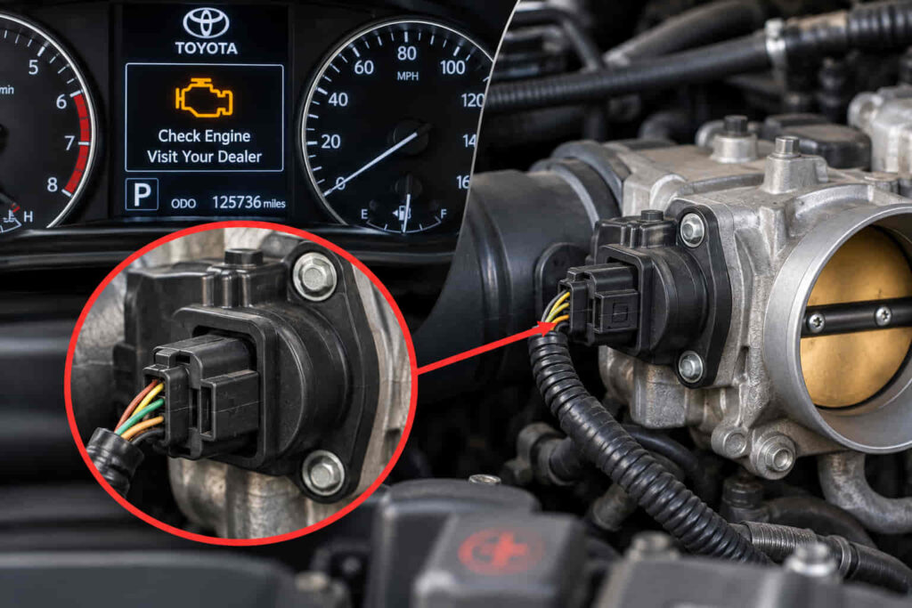
Toyota P1155 is a manufacturer-specific diagnostic trouble code related to the Air-Fuel Ratio (A/F) sensor heater circuit on Bank 2 Sensor 1 on applicable Toyota vehicles. The Engine Control Module (ECM) sets this code when it detects that the heater circuit is not operating within the expected electrical range. Because the heater helps the A/F sensor reach its operating temperature quickly, a malfunction can delay accurate air-fuel mixture monitoring and trigger the Check Engine Light.
A P1155 code does not automatically mean the Air-Fuel Ratio sensor needs to be replaced. The fault can originate from the sensor heater itself, damaged wiring, a loose or corroded electrical connector, an open or short circuit, or a problem with the circuit supplying power to the heater. The exact location of Bank 2 Sensor 1 also depends on the Toyota model, engine, and cylinder-bank configuration, so identifying the correct sensor is an important part of diagnosis.
Diagnosing Toyota P1155 therefore requires checking the heater circuit and its electrical connections before replacing components. This guide explains what P1155 means, what causes it, which symptoms it can produce, how serious it is, and how to diagnose and fix the underlying fault.
What Does the P1155 Code Mean on a Toyota?
Toyota P1155 indicates a malfunction involving the Air-Fuel Ratio (A/F) sensor heater circuit for Bank 2 Sensor 1 on applicable Toyota vehicles. Bank 2 identifies the cylinder bank opposite the bank containing cylinder No. 1, while Sensor 1 identifies the upstream sensor positioned before the catalytic converter. The exact sensor position depends on the engine configuration, so the vehicle’s model, model year, and engine should be confirmed before locating or replacing the sensor.
The A/F sensor measures oxygen-related conditions in the exhaust so the Engine Control Module (ECM) can monitor and adjust the air-fuel mixture. For the sensor to provide useful feedback soon after a cold start, it needs to reach its required operating temperature quickly. Toyota uses an electrical heater inside the sensor to accelerate this process instead of relying entirely on exhaust heat.
P1155 is triggered when the ECM detects an abnormal condition in this heater circuit. The monitored circuit includes more than the sensing element itself because electrical current must travel through the power supply, wiring, connector, and heater element. An open circuit, short circuit, excessive resistance, or failed heater can therefore prevent the circuit from operating as expected and cause the ECM to store P1155.
This distinction is important during diagnosis. P1155 identifies a heater-circuit malfunction; it does not prove by itself that the complete A/F sensor has failed. Replacing Bank 2 Sensor 1 without testing its circuit can leave the original problem unresolved when damaged wiring, poor terminal contact, or another electrical fault is responsible.
What Are the Causes of Toyota Code P1155?
Toyota P1155 is caused when the Bank 2 Sensor 1 A/F sensor heater circuit cannot operate within the range expected by the ECM. The fault can originate inside the sensor or elsewhere in the electrical circuit, which is why the stored code should be treated as the starting point for diagnosis rather than as an instruction to replace a specific component.
A failed heater element inside the Air-Fuel Ratio sensor is a direct cause of P1155. The heater is subjected to repeated heating and cooling cycles whenever the engine operates. An internal electrical failure can eventually prevent the heater from drawing the expected current. When this occurs, the sensor may still physically remain in the exhaust system, but its heater circuit no longer behaves within the parameters monitored by the ECM.
Damaged wiring is another important cause because the A/F sensor operates close to the exhaust system. Wiring routed near hot exhaust components can develop damaged insulation, broken conductors, or short circuits if the harness contacts a hot surface or is incorrectly positioned. An open conductor interrupts current through the heater, while a short can change the electrical characteristics of the circuit enough for the ECM to recognize a malfunction.
The electrical connector can produce the same code even when the sensor itself remains functional. Loose terminals, corrosion, contamination, damaged pins, or poor connector contact increase resistance or interrupt the electrical path between the sensor and the vehicle harness. A visual inspection is therefore useful, but it does not replace electrical testing because a conductor or terminal can have excessive resistance without obvious external damage.
A problem with heater-circuit power or its associated electrical path can also produce P1155. The technician should confirm that the circuit receives the specified power and has the required continuity according to the wiring diagram and service information for the specific Toyota model and engine. Testing against vehicle-specific specifications is important because connector pin assignments and circuit layouts are not identical across every Toyota that can display this code.
An ECM-related fault should be considered only after the sensor heater, wiring, connector, power supply, and relevant circuit conditions have been verified. The diagnostic sequence should move from the heater circuit and its physical connections toward the control side rather than assuming the ECM is defective. This approach isolates the failed part of the circuit and reduces the risk of replacing a functional A/F sensor or another expensive component.
Read more: Toyota C0210
What Symptoms Can Toyota Code P1155 Cause?
The most consistent symptom of Toyota P1155 is an illuminated Check Engine Light, while noticeable changes in engine operation may be limited or absent. P1155 concerns the heater circuit for the Bank 2 Sensor 1 Air-Fuel Ratio sensor rather than directly identifying a mechanical engine failure. A Toyota can therefore continue to start, idle, and drive normally even though the ECM has detected an electrical problem and stored the diagnostic trouble code.
The Check Engine Light appears because the ECM monitors the A/F sensor heater circuit and recognizes when its electrical behavior falls outside the expected operating conditions. The heater is especially important after a cold start because the exhaust has not yet supplied enough heat to bring the sensor rapidly to its operating temperature. A malfunctioning heater can extend the period before the sensor provides the feedback expected by the engine management system.
Fuel-control behavior can also be affected while the A/F sensor is not operating as intended, although P1155 alone does not establish that the vehicle will have poor fuel economy, rough idle, hesitation, or another specific drivability symptom. Those symptoms require further diagnosis because additional engine, intake, fuel, ignition, or exhaust faults can produce similar behavior. The presence of another DTC alongside P1155 is particularly important because it can change the diagnostic direction.
The symptom pattern therefore provides useful diagnostic context. A vehicle with P1155 and no noticeable drivability problem still requires heater-circuit testing, while a vehicle with P1155 plus rough running or additional fault codes requires the technician to evaluate those conditions together. The absence of obvious driving symptoms does not mean the heater circuit is operating correctly.
How Serious Is the P1155 Code on a Toyota?
Toyota P1155 is generally a fault that should be diagnosed promptly, but the code alone does not necessarily mean the vehicle must be stopped immediately. Because the malfunction involves the A/F sensor heater circuit, many affected vehicles can remain driveable while the Check Engine Light is illuminated. Continued vehicle operation, however, should not be used as evidence that the fault can be ignored.
The immediate effect depends on whether P1155 exists by itself or appears with additional faults. A heater-circuit malfunction primarily interferes with how quickly the A/F sensor reaches the conditions needed for proper feedback, particularly after startup. If the vehicle otherwise starts and runs normally and the Check Engine Light is steady, the appropriate response is to schedule diagnosis rather than automatically replace the sensor.
The situation requires greater attention when P1155 appears with significant drivability problems or other diagnostic trouble codes. Rough running, repeated stalling, substantial loss of power, abnormal exhaust behavior, or a flashing Check Engine Light indicates that the vehicle may have a problem beyond the isolated heater-circuit code. Those conditions should be diagnosed according to the complete set of symptoms and stored DTCs rather than attributed to P1155 without testing.
Driving for an extended period without diagnosis is also a poor repair strategy because an unresolved electrical fault remains present even when the vehicle feels normal. The correct response to P1155 is to identify whether the failure is in the A/F sensor heater, wiring, connector, power path, or another part of the monitored circuit. Establishing that cause determines both the actual severity of the problem and the repair required.
How Do You Diagnose Toyota Code P1155?
Diagnosing Toyota P1155 requires testing the Bank 2 Sensor 1 Air-Fuel Ratio sensor heater circuit before replacing the sensor. The diagnostic process should determine whether the malfunction originates inside the sensor heater or in the wiring, connector, power supply, or control side of the circuit. Because electrical specifications and connector layouts vary by Toyota model and engine, resistance and voltage measurements should be compared with the service information for the specific vehicle.
Diagnosis should begin by confirming P1155 with an OBD-II scan tool and checking for additional stored or pending diagnostic trouble codes. Related codes can identify another circuit problem or provide context that changes the direction of testing. Freeze-frame data, when available, can also show engine operating conditions when the ECM detected the fault. Clearing P1155 before recording this information removes diagnostic evidence that may help identify when the malfunction occurs.
The Bank 2 Sensor 1 wiring and connector should then be inspected before electrical measurements are made. This sensor operates near hot exhaust components, making its harness particularly important to examine for melted insulation, abrasion, broken conductors, incorrect routing, loose terminals, corrosion, or connector damage. A harness that has contacted the exhaust can create an open or short circuit even when the A/F sensor itself remains functional. Connector damage can similarly interrupt current or introduce excessive resistance into the heater circuit.
The heater element should be tested after the external circuit has been inspected. Resistance across the appropriate heater terminals can indicate whether the element has electrical continuity, but the measurement must be evaluated against Toyota’s specification for the exact sensor and vehicle application. An open heater circuit or a resistance measurement outside the specified range supports a heater failure diagnosis. A resistance value within specification means the rest of the circuit still needs to be tested rather than assuming the sensor is good or bad from the DTC alone.
The heater’s power circuit should also be verified. The technician should use the applicable wiring diagram to identify the correct terminals and determine whether the circuit receives the specified voltage under the required test conditions. If power is absent, the diagnostic path moves away from immediate sensor replacement and toward the power supply, wiring, connectors, and other components in that electrical path. Continuity testing can then identify an open conductor, while appropriate circuit testing can reveal a short or excessive resistance.
The control side of the heater circuit should be evaluated only after the sensor, connector, wiring, and power path have been checked. The ECM participates in monitoring and controlling the circuit, but an ECM should not be condemned simply because P1155 remains stored. A control-module diagnosis requires evidence that the external circuit meets the applicable specifications while the commanded or monitored circuit behavior remains incorrect.
The final diagnosis should identify a failed component or electrical condition rather than merely repeat the P1155 description. A failed heater element supports A/F sensor replacement, damaged wiring supports harness repair, poor terminal contact supports connector repair, and missing circuit power requires tracing the affected electrical path. This cause-based approach prevents the common mistake of replacing Bank 2 Sensor 1 solely because an OBD-II scanner displays P1155.
How Do You Fix Toyota Code P1155?
Fixing Toyota P1155 requires repairing the specific fault found in the Bank 2 Sensor 1 Air-Fuel Ratio sensor heater circuit rather than automatically replacing the sensor. The correct repair depends on the diagnostic result. A failed heater inside the A/F sensor requires sensor replacement, damaged wiring requires circuit repair, poor terminal contact requires connector repair, and a power-supply fault requires the affected electrical path to be restored.
Replacing the Bank 2 Sensor 1 A/F sensor is appropriate when electrical testing confirms that its internal heater has failed or operates outside the specification provided for the vehicle. The replacement sensor must match the Toyota model, model year, engine, and sensor position because Bank 2 Sensor 1 is not interchangeable with every oxygen or A/F sensor used on the vehicle. Parts catalogs may also use terms such as air-fuel ratio sensor, oxygen sensor, or upstream sensor, so identifying the component by its actual application and position reduces the risk of installing the wrong part.
The sensor should not be replaced when testing identifies an open or short in the external wiring. Damaged conductors and insulation need to be repaired so the heater receives the electrical conditions required by the circuit. Wiring near the exhaust also needs to be routed and secured correctly after repair. Restoring continuity without correcting a harness that contacts a hot exhaust component can allow the same damage and P1155 code to return.
Connector faults require the same cause-based approach. Corroded, loose, contaminated, pushed-back, or damaged terminals can prevent a functional heater from operating correctly. The affected connector or terminal should be repaired when it cannot maintain reliable electrical contact. Installing a new A/F sensor while leaving a defective vehicle-side connector unchanged does not remove the underlying circuit fault.
A missing power supply must be traced through the applicable wiring diagram rather than bypassed by replacing unrelated components. The repair should restore the original electrical path and then be verified under the operating conditions specified for that Toyota. ECM replacement should remain a late-stage repair decision because the sensor heater, wiring, connectors, power path, and associated circuit conditions need to be verified before the control module is considered responsible.
After the repair, the stored P1155 code can be cleared with a compatible scan tool and the vehicle should be operated under appropriate conditions before the system is checked again. A successful repair is confirmed when the heater circuit operates correctly and P1155 does not return, not simply when the Check Engine Light disappears after the code is erased. If P1155 returns, the circuit requires further diagnosis because clearing a DTC resets the warning but does not correct the electrical condition that originally caused it.
Where Is Bank 2 Sensor 1 Located on a Toyota?
Bank 2 Sensor 1 is the upstream Air-Fuel Ratio sensor installed on the cylinder bank opposite the bank containing cylinder No. 1 on applicable Toyota engines. “Bank 2” identifies the cylinder bank, while “Sensor 1” identifies the sensor positioned upstream of the catalytic converter. For Toyota P1155 diagnosis, these two identifiers must be considered together because replacing a sensor on the wrong bank will not repair the heater-circuit fault associated with the code.
The exact physical location of Bank 2 Sensor 1 depends on the Toyota model, model year, engine family, and exhaust layout. On an engine with two cylinder banks, each bank can have its own upstream sensor monitoring exhaust before the catalytic converter. Bank 1 is the side containing cylinder No. 1, and Bank 2 is the opposite side. Sensor 1 is the upstream sensor associated with that bank rather than the downstream sensor used after the catalytic converter.
The safest way to locate the correct sensor is to identify the engine installed in the vehicle and use the corresponding Toyota service information or an accurate engine-specific diagram. Guessing the bank from the driver’s side or passenger’s side is unreliable because engine orientation and cylinder numbering vary between applications. The electrical connector should also be traced to the correct sensor before testing because the diagnostic procedure for P1155 concerns the heater circuit connected specifically to Bank 2 Sensor 1.
This distinction becomes especially important when purchasing a replacement. A Toyota may use multiple exhaust sensors that look similar but have different functions, electrical characteristics, connectors, or installation positions. The correct replacement for P1155 should therefore be selected by vehicle application, engine, and Bank 2 Sensor 1 position rather than appearance alone.
How Much Does It Cost to Fix Toyota Code P1155?
The cost to fix Toyota P1155 depends on whether the confirmed fault is the A/F sensor, wiring, connector, power circuit, or another part of the heater circuit. P1155 itself does not determine a single repair price because the DTC identifies the affected circuit but does not identify which component in that circuit has failed.
An A/F sensor replacement involves the price of the correct Bank 2 Sensor 1 unit plus labor for removal, installation, and verification. The final amount can vary substantially between Toyota models because sensor accessibility, engine configuration, parts pricing, labor rates, and the use of original-equipment or alternative replacement components differ. A sensor located in an easily accessible section of the exhaust requires a different amount of labor from one surrounded by components that restrict tool access.
A wiring or connector fault creates a different cost structure. A small section of heat-damaged wiring or an individual terminal may require less in parts than a complete A/F sensor, but electrical diagnosis and harness repair add labor. More extensive heat damage can require additional wiring work. This is one reason replacing the sensor before testing the circuit can increase the total repair cost: the owner may pay for a functional component while the actual wiring fault remains.
Diagnostic labor should also be considered part of the repair cost when the cause is not already confirmed. Proper testing requires identifying the correct sensor, inspecting the harness, checking the connector, measuring the heater circuit, and verifying the relevant power and control paths. Paying for diagnosis can prevent unnecessary parts replacement, particularly when the P1155 code is caused by an external circuit fault rather than the A/F sensor itself.
A reliable estimate therefore requires the Toyota model, model year, engine, local labor rate, and confirmed cause of P1155. The repair price should be calculated from the diagnosed failure rather than from the trouble code alone. Once testing identifies whether the vehicle needs an A/F sensor, connector repair, wiring repair, or another electrical correction, parts and labor can be estimated accurately for that specific vehicle.
Can a Bad Oxygen Sensor Cause Toyota Code P1155?
A failed Air-Fuel Ratio sensor can cause Toyota P1155 when the heater element inside the Bank 2 Sensor 1 unit is defective, but P1155 does not prove that the entire sensor has failed. This distinction matters because the code refers specifically to the heater circuit. An external wiring, connector, power-supply, or circuit fault can create the same DTC even when the sensing portion of the component is not the source of the problem.
The terms “oxygen sensor” and “Air-Fuel Ratio sensor” are sometimes used interchangeably when discussing Toyota exhaust sensors, but they should not automatically be treated as identical components during diagnosis or parts selection. For P1155, the relevant component on applicable Toyota vehicles is the Bank 2 Sensor 1 A/F sensor and its heater circuit. The correct replacement must therefore be identified using the vehicle model, model year, engine, and sensor position rather than purchasing a generic O2 sensor based only on the trouble-code description.
The heater is integrated into the sensor assembly and helps bring the sensing element to its required operating temperature after engine startup. If the heater element develops an internal open circuit or otherwise operates outside the expected electrical range, replacing the correct A/F sensor can resolve P1155. Sensor replacement is not the correct repair when electrical testing instead finds damaged harness wiring, poor terminal contact, missing circuit power, or another external electrical fault.
P1155 should therefore be interpreted as evidence of a Bank 2 Sensor 1 heater-circuit problem, not as automatic evidence that an oxygen sensor needs replacement. Testing the heater resistance, circuit power, wiring, and connector against the specifications for the specific Toyota application provides a stronger diagnosis than replacing the sensor based on the DTC alone.
What Is the Difference Between Toyota P1155 and P1135?
Toyota P1155 and P1135 are related diagnostic trouble codes that can identify A/F sensor heater-circuit faults on different cylinder banks in applicable Toyota applications. P1155 is associated with the Bank 2 Sensor 1 heater circuit in the context covered by this article, while P1135 is commonly associated with the corresponding Bank 1 Sensor 1 A/F sensor heater circuit. The practical difference is therefore the cylinder bank being monitored rather than an instruction to perform an entirely different type of diagnosis.
Bank identification is critical when distinguishing these codes. Bank 1 contains cylinder No. 1, while Bank 2 is the opposite cylinder bank on an engine that uses two banks. Sensor 1 identifies the upstream sensor located before the catalytic converter for that bank. As a result, P1135 directs diagnosis toward the upstream A/F sensor heater circuit on Bank 1, whereas P1155 directs diagnosis toward the upstream heater circuit on Bank 2 for Toyota applications using these definitions.
The diagnostic logic remains similar for both codes. The relevant sensor heater, electrical connector, wiring, power path, and control circuit need to be evaluated before a component is replaced. For example, P1155 with a confirmed open heater inside Bank 2 Sensor 1 points toward replacement of that sensor, while P1135 with heat-damaged wiring on the Bank 1 circuit requires wiring repair rather than replacement of the Bank 2 sensor.
The distinction also prevents an expensive parts-selection error. P1155 should direct attention to the Bank 2 Sensor 1 circuit, while P1135 should direct attention to the Bank 1 Sensor 1 circuit on applicable Toyota configurations. Vehicle-specific service information should still be checked before testing or replacing either sensor because Toyota DTC definitions, engine layouts, wiring, and component specifications must be matched to the exact vehicle application.
How Can You Prevent Toyota P1155 From Returning?
Preventing Toyota P1155 from returning requires correcting the underlying Bank 2 Sensor 1 A/F sensor heater-circuit fault and verifying the complete circuit after the repair. Simply clearing the diagnostic trouble code removes the stored fault from the ECM but does not repair the condition that triggered it. A lasting repair must address the failed sensor heater, damaged wiring, defective connector, power-supply problem, or other confirmed electrical fault.
Wiring condition is particularly important because the Bank 2 Sensor 1 harness operates close to exhaust components. A repaired wire should be routed and secured so that its insulation cannot contact a hot exhaust surface or become damaged by vibration and abrasion. Repairing a broken conductor without correcting the routing that caused the original damage can allow the circuit to fail again and P1155 to return.
Electrical connectors should also remain secure, clean, and physically intact after the repair. Loose terminals, damaged pins, corrosion, and poor terminal contact can introduce resistance or interrupt heater current. When connector damage caused the original fault, restoring reliable electrical contact is necessary before the circuit can be considered repaired. Installing a new A/F sensor while retaining a damaged vehicle-side connector can reproduce the same heater-circuit malfunction.
Correct parts selection reduces another source of repeat faults. The replacement A/F sensor should match the Toyota model, model year, engine, and Bank 2 Sensor 1 application. A component that physically fits the exhaust system is not automatically electrically correct for the vehicle. Matching the replacement to the exact application helps ensure that the heater and sensor operate according to the specifications expected by the ECM.
The final preventive step is post-repair verification. After P1155 is cleared, the vehicle should be operated under the appropriate conditions and scanned again for stored or pending codes. The repaired circuit should also be checked if the diagnostic procedure requires additional electrical verification. Toyota P1155 can be considered resolved when the underlying heater-circuit fault has been corrected and the code does not return after verification, rather than when the Check Engine Light has merely been reset.