Rebuilding a 4L60E transmission involves disassembling the transmission, inspecting its internal components, replacing worn or damaged parts, and reassembling the unit according to manufacturer specifications. The process restores the transmission’s mechanical and hydraulic functions by addressing problems such as slipping gears, delayed engagement, loss of third or fourth gear, and damaged clutch assemblies.
A complete 4L60E transmission rebuild requires several essential components, including friction plates, steel plates, seals, gaskets, and bushings. Depending on their condition, the 3-4 clutch pack, 2-4 band, sun shell, oil pump, and valve body may also require repair or replacement. Specialized tools, including a clutch spring compressor, snap-ring pliers, torque wrench, and dial indicator, are necessary for disassembly, assembly, and clearance measurements.
The rebuilding procedure consists of seven main stages: transmission removal, disassembly, component inspection, parts replacement, reassembly, installation, and performance testing. Each stage requires accurate component positioning, proper lubrication, and adherence to specifications for the specific 4L60E version. This guide explains the tools, replacement parts, rebuilding procedures, common mistakes, and costs involved in restoring a 4L60E automatic transmission.
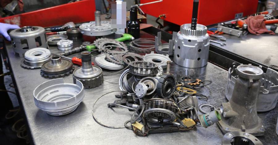
What Is Involved in Rebuilding a 4L60E Transmission?
Rebuilding a 4L60E transmission involves seven main stages: removal, disassembly, inspection, parts replacement, reassembly, installation, and performance testing. Each stage restores or verifies a specific part of the transmission’s operation, including gear engagement, hydraulic pressure regulation, and torque transfer. A complete rebuild addresses internal wear and damage rather than replacing only the component responsible for an immediate failure.
The process begins with diagnosing the transmission’s symptoms and removing the unit from the vehicle. Once the transmission is disassembled, the clutch packs, planetary gearsets, sun shell, oil pump, valve body, and other internal components are inspected for wear or mechanical damage. For example, burnt friction plates in the 3-4 clutch pack can cause slipping or loss of third and fourth gears, while a damaged sun shell can result in the loss of reverse, second, and fourth gears. Identifying these failures helps determine which components require replacement.
Worn friction plates, steel plates, seals, gaskets, and bushings are replaced as required during the rebuild. The technician also checks clutch clearances, transmission endplay, sealing surfaces, and hydraulic components against specifications for the applicable 4L60E version. Incorrect clearances or damaged seals can cause insufficient clutch holding pressure, resulting in slipping, overheating, or premature failure after reassembly.
The final stages involve reinstalling the internal assemblies, fitting the torque converter correctly, mounting the transmission, and filling it with the specified automatic transmission fluid. Functional testing verifies gear engagement, shift operation, hydraulic pressure where required, and the absence of fluid leaks. A successful rebuild must also address the original cause of failure and remove contamination from the transmission cooler and lines to prevent debris from damaging the rebuilt components.
What Tools Do You Need to Rebuild a 4L60E Transmission?
A 4L60E transmission rebuild requires three categories of equipment: general hand tools, specialized transmission tools, and measuring instruments. Vehicle removal also requires appropriate lifting and support equipment. Each tool serves a specific purpose in disassembling tightly fitted components, installing clutch assemblies, measuring internal clearances, or preventing damage during installation.
General hand tools include metric socket sets, ratchets, extensions, torque wrenches, screwdrivers, picks, and snap-ring pliers. These tools are used to remove the transmission pan, valve body, bellhousing fasteners, retaining rings, and external components. A torque wrench is essential during reassembly because transmission fasteners require specified tightening values. Incorrect torque can damage aluminum threads, distort components, or create sealing problems.
Specialized transmission tools include a clutch spring compressor, transmission pump removal tools, suitable assembly fixtures, and seal installation tools. A clutch spring compressor allows the technician to compress return springs and remove retaining rings without damaging the clutch drum. Pump removal tools help extract the oil pump without prying against precision-machined sealing surfaces. A transmission holding fixture keeps the case stable while internal assemblies are removed or installed.
Measuring instruments include a dial indicator, feeler gauges, and suitable precision measuring tools for checking endplay, clutch pack clearance, and component wear. A dial indicator measures axial movement in rotating assemblies, while feeler gauges help verify clearances where the service procedure specifies their use. These measurements determine whether selective components, clutch assemblies, and other parts meet the requirements of the specific transmission version.
Removing and reinstalling the 4L60E also requires a transmission jack, properly rated vehicle lift or jack stands, and suitable engine support equipment. A stable workbench, organized parts trays, lint-free cleaning materials, and appropriate cleaning solutions help prevent contamination and component misplacement. The correct factory service manual or equivalent transmission-specific technical documentation is necessary for verifying assembly sequences, torque specifications, and clearance limits before beginning the rebuild.
What Parts Are Needed for a 4L60E Transmission Rebuild?
A 4L60E transmission rebuild requires a master rebuild kit containing friction plates, steel plates, seals, gaskets, and other components needed to restore the transmission’s internal operation. Additional replacement parts may include the 2-4 band, sun shell, bushings, oil pump components, and valve body parts, depending on their condition. The correct parts must match the transmission’s production year, internal design, and component specifications because 4L60E transmissions underwent several design revisions.
A master rebuild kit typically includes clutch friction plates, steel separator plates, rubber seals, O-rings, sealing rings, and transmission gaskets. Friction plates and steel plates form the clutch assemblies responsible for engaging specific gear ratios. Rubber seals and sealing rings maintain hydraulic pressure within the transmission’s fluid circuits. Worn friction material reduces torque-holding capacity, while damaged seals allow pressure leakage that can cause delayed engagement or slipping. Kit contents vary by manufacturer, so the included components must be verified before purchasing.
The 3-4 clutch pack and 2-4 band are critical components that require careful inspection during rebuilding. The 3-4 clutch assembly transfers torque during third- and fourth-gear operation, while the 2-4 band holds the reverse input drum during second- and fourth-gear operation. Burnt friction plates, warped steel plates, damaged clutch drums, or a worn band indicate problems that must be corrected before reassembly. Clutch clearance must also be measured because installing new friction plates without verifying the assembled clearance can lead to dragging, slipping, or premature clutch failure.
The sun shell, planetary gearsets, and transmission pump must be inspected for mechanical damage and excessive wear. The sun shell connects elements of the planetary geartrain, and damaged splines or a fractured shell can interrupt power transfer in specific gear ranges. Planetary gearsets require inspection for damaged teeth, worn bearings, and excessive movement. The oil pump must be checked for scoring, damaged sealing surfaces, and wear that could reduce hydraulic pressure. Components outside the applicable service limits require repair or replacement.
The valve body, shift solenoids, pressure control solenoid, and torque converter also require evaluation. The valve body directs transmission fluid through hydraulic passages to control clutch and band application, while electronic solenoids regulate shifting and pressure commands. Worn valve bores, damaged separator plate components, or malfunctioning solenoids can produce shifting problems even after the mechanical assemblies have been rebuilt. A contaminated or internally damaged torque converter must be replaced or professionally remanufactured because trapped debris can enter the rebuilt transmission.
Selecting replacement parts should follow a complete inspection rather than a fixed replacement list. A standard rebuild kit addresses common wear items, but damaged hard parts, hydraulic components, and electronic controls require separate evaluation. Identifying these requirements before reassembly prevents incompatible parts, unresolved mechanical faults, and unnecessary repeat repairs.
How Do You Remove a 4L60E Transmission Before Rebuilding It?
Removing a 4L60E transmission requires safely supporting the vehicle, disconnecting the transmission from the drivetrain and electrical systems, separating the torque converter from the engine, and lowering the transmission with a suitable jack. The removal sequence varies between rear-wheel-drive and four-wheel-drive vehicles because four-wheel-drive applications include a transfer case and additional drivetrain components. The correct vehicle-specific service procedure must be followed to prevent damage to the transmission, engine, and surrounding components.
Step 1: Prepare and support the vehicle. Park the vehicle on a level surface, engage the parking brake, secure the wheels, and disconnect the negative battery cable. Raise the vehicle using an appropriately rated lift or jack and support it securely at the manufacturer’s designated lifting points. Never work beneath a vehicle supported only by a hydraulic jack. Allow hot exhaust and transmission components to cool before beginning removal. Position a drain pan beneath the transmission and drain the fluid through the pan when required by the service procedure.
Step 2: Disconnect the external transmission connections. Remove the driveshaft after marking its installed orientation where applicable. Disconnect the transmission electrical connector, shift linkage, cooler lines, and any brackets or wiring attached to the transmission case. Cap or plug open cooler lines to limit fluid loss and prevent contamination. Remove exhaust components or other obstructions when necessary to create sufficient working clearance. On four-wheel-drive vehicles, the transfer case and associated components must be disconnected or removed according to the vehicle-specific procedure.
Step 3: Disconnect the torque converter from the engine. Remove the torque converter access cover or inspection cover to reach the converter-to-flexplate fasteners. Rotate the engine manually using the appropriate crankshaft turning method to access each fastener, and remove the fasteners while preventing unintended engine rotation. The torque converter must remain supported within the transmission during removal. Separating the converter from the flexplate before lowering the transmission prevents damage to the converter, flexplate, and transmission pump.
Step 4: Support the engine and transmission. Position a transmission jack beneath the transmission and secure the unit using the jack’s retaining system. Support the rear of the engine as required by the vehicle manufacturer before removing the transmission crossmember or mount. Remove the crossmember and transmission mount fasteners while maintaining stable support. The engine must not be allowed to tilt excessively because uncontrolled movement can damage engine mounts, exhaust connections, wiring, or cooling components.
Step 5: Remove the bellhousing bolts and separate the transmission. Remove the bellhousing fasteners while supporting the transmission’s weight. Check that all electrical connections, brackets, cooler lines, and mechanical attachments have been disconnected. Move the transmission straight rearward until the input assembly and torque converter are clear of the engine. Do not use the bellhousing bolts to force separation or allow the transmission to hang from the engine. Once separated, lower the transmission gradually while checking for interference with the vehicle frame and surrounding components.
Step 6: Secure the transmission for disassembly. Lower the transmission onto a stable work surface or suitable transmission holding fixture. Secure the torque converter before moving the unit, then remove it carefully while accounting for the fluid remaining inside. Inspect the converter hub, transmission case, bellhousing, and external sealing surfaces for visible damage. Record the transmission identification information and note any signs of fluid leakage, overheating, or physical damage before opening the case.
After removal, clean the transmission exterior to prevent dirt from entering the hydraulic passages during disassembly. Keep the removed fasteners, brackets, and external components organized according to their installation positions. The transmission is ready for internal disassembly once it is securely mounted, externally cleaned, and correctly identified.
How Do You Disassemble a 4L60E Transmission?
Disassembling a 4L60E transmission involves removing the transmission pan, valve body, oil pump, clutch assemblies, 2-4 band, and planetary geartrain in a controlled sequence. The process exposes internal components for inspection and identifies damage that may not be visible during external diagnosis. Proper disassembly requires a clean workbench, a stable transmission holding fixture, and organized storage for fasteners, retaining rings, selective washers, and hydraulic components.
Before disassembly, record the transmission identification information and inspect the fluid for signs of internal damage. Darkened fluid, burnt odors, metallic particles, and friction material in the transmission pan can indicate clutch deterioration, geartrain damage, or excessive component wear. Photographing each assembly before removal helps preserve the original position and orientation of components. The exact removal sequence must follow the service information for the specific 4L60E version.
How Do You Remove the Transmission Pan and Valve Body?
To remove the 4L60E transmission pan and valve body, drain the remaining fluid, remove the pan and filter, disconnect the internal electrical components, and carefully separate the valve body from the transmission case. These components form part of the hydraulic control system responsible for directing transmission fluid to the clutch packs, band servo, and torque converter clutch.
Step 1: Remove the transmission pan and filter. Position a drain container beneath the transmission and loosen the pan bolts gradually to control fluid discharge. Remove the pan and inspect its bottom surface and magnet for metal particles, clutch material, or other debris. A light coating of fine metallic residue may develop during normal operation, while substantial metal fragments or excessive friction material indicate internal wear. Remove the transmission filter and inspect its seal and mounting area for damage.
Step 2: Disconnect the internal electrical components. Identify the wiring connections for the shift solenoids, pressure control solenoid, torque converter clutch controls, and other electrical components fitted to the transmission version. Release the connectors using the appropriate locking features rather than pulling on the wires. Inspect the harness for damaged insulation, loose terminals, and fluid-related deterioration. Label the connections when necessary to prevent incorrect installation during reassembly.
Step 3: Remove the valve body assembly. Remove the valve body retaining bolts according to the applicable service procedure, recording their locations because bolt lengths and positions can differ. Carefully lower the valve body while accounting for the manual valve connection, hydraulic components, and any checkballs that may be retained by the separator plate or case. Avoid tilting or shaking the assembly because small components can become displaced.
Step 4: Inspect the separator plate and hydraulic components. Remove the separator plate and gaskets as specified for the transmission version. Record the location of checkballs, screens, and related hydraulic components before separating them. Inspect the separator plate for damaged holes, gasket deterioration, and wear caused by repeated checkball contact. Incorrect checkball placement or mismatched gaskets can redirect hydraulic pressure and produce shifting problems after rebuilding.
Place the valve body, separator plate, solenoids, and associated components in separate labeled trays. Keep hydraulic passages protected from dust, abrasive particles, and loose cleaning materials. Detailed valve body cleaning and component testing should take place during the inspection stage rather than during initial removal.
How Do You Remove the Oil Pump and Internal Components?
Removing the 4L60E oil pump and internal components requires extracting the pump assembly, releasing the clutch and band assemblies, and removing the planetary geartrain in the correct order. These components transfer engine torque through different gear ratios and rely on hydraulic pressure to engage or release specific elements. Maintaining their original orientation is essential because selective washers, bearings, and retaining components determine internal clearances.
Step 1: Remove the oil pump assembly. Position the transmission securely with access to the front pump. Remove the pump retaining bolts and use the appropriate pump removal tool to extract the assembly evenly from the case. Avoid prying against machined surfaces because scratches or distortion can create hydraulic leaks. Once removed, inspect the pump-to-case sealing area and store the pump where its gears, sealing rings, and mating surfaces cannot be damaged.
Step 2: Remove the input housing and clutch assemblies. Carefully extract the input housing and associated clutch assemblies according to the transmission-specific disassembly sequence. Record the location of thrust bearings, selective washers, and retaining components as they are exposed. The input housing contains clutch assemblies that control torque transfer through the transmission. Damage to the 3-4 clutch pack, including burnt friction plates or distorted steel plates, is an important finding when investigating third- or fourth-gear slipping.
Step 3: Remove the 2-4 band and related components. Release and remove the band according to the service procedure, taking care not to damage the friction lining or surrounding drum surfaces. Inspect the band for glazing, cracking, uneven wear, and friction material separation. Examine the reverse input drum surface for scoring, discoloration, or other signs of excessive heat. The 2-4 band applies holding force to the reverse input drum during second- and fourth-gear operation, so damage to either contact surface can interfere with proper gear engagement.
Step 4: Remove the planetary geartrain and sun shell. Continue disassembly by removing the applicable retaining rings, geartrain assemblies, sun shell, and associated thrust components in the specified sequence. Keep each bearing and selective washer with its original assembly until measurements establish whether replacement or adjustment is required. Inspect the sun shell splines and geartrain components for obvious cracks, broken teeth, or excessive wear. A damaged sun shell can interrupt the mechanical connections required for reverse, second, and fourth gears.
Step 5: Remove the remaining internal components. Extract the remaining output-related assemblies, retaining components, and other internal parts according to the transmission configuration. Use suitable snap-ring pliers and assembly tools to avoid damaging retaining grooves or machined surfaces. Do not force components that remain engaged or secured by hidden retainers. If an assembly resists removal, verify the service procedure and identify the obstruction before applying additional force.
After disassembly, arrange the internal components in their removal order and separate reusable parts from visibly damaged components. Keep clutch packs, bearings, thrust washers, and selective components identified until inspection and measurement are complete. Clean the transmission case and accessible passages using methods compatible with the materials and components involved, then dry and protect the cleaned surfaces against contamination.
A fully disassembled 4L60E transmission is ready for detailed inspection when the major mechanical and hydraulic assemblies have been removed, identified, and organized. The next stage determines which parts meet service specifications, which require replacement, and whether damage to the case or other major components makes rebuilding impractical.
How Do You Inspect 4L60E Transmission Components for Damage?
Inspecting 4L60E transmission components requires checking the clutch packs, planetary gearsets, sun shell, oil pump, and valve body for wear, deformation, and mechanical damage. Each component must be examined for visible defects and measured against the specifications for the applicable transmission version. This inspection identifies the original failure, determines which parts require replacement, and prevents damaged components from being reused during the rebuild.
The inspection should begin with components associated with the transmission’s original symptoms. For example, slipping in third or fourth gear warrants examination of the 3-4 clutch assembly, while the simultaneous loss of reverse, second, and fourth gears can indicate sun shell damage. However, symptoms alone do not confirm a failed component because hydraulic pressure loss, valve body wear, and electronic control problems can produce similar operating conditions.
How Do You Inspect the Clutch Packs and Geartrain?
To inspect the 4L60E clutch packs and geartrain, examine the friction plates, steel plates, clutch drums, sun shell, planetary gears, bearings, and thrust surfaces for wear or damage. The inspection must also include clutch clearance measurements and checks for excessive movement within the geartrain. Components with cracked surfaces, distorted friction elements, or measurements outside service limits must be repaired or replaced.
Inspect the 3-4 clutch pack by removing its retaining components and releasing the clutch return spring assembly with a suitable compressor. Examine each friction plate for burnt material, glazing, missing friction lining, and uneven wear. Inspect the steel plates for heat discoloration, warping, and scoring. Darkened or damaged friction plates can indicate clutch slippage caused by insufficient hydraulic pressure, incorrect clearance, or excessive heat. Check the clutch drum, piston, and sealing surfaces for cracks, scoring, or wear that could prevent the assembly from holding pressure.
Measure the assembled clutch pack clearance using the method specified for the transmission version. Excessive clearance increases the distance the piston must travel before the clutch engages, potentially delaying application and increasing heat generation. Insufficient clearance can prevent complete clutch release, creating friction and overheating. The correct clearance depends on the clutch configuration and applicable service specifications rather than a single universal measurement.
Inspect the planetary gearsets and sun shell for damaged teeth, worn splines, cracked components, and excessive bearing movement. Rotate the planetary pinions by hand to check for roughness, binding, or abnormal looseness. Examine thrust washers and bearings for scoring, pitting, and heat damage. The sun shell requires particular attention around its splined hub and connecting surfaces because fractures or stripped splines can interrupt torque transfer through the geartrain. Any gearset with damaged teeth or excessive internal movement requires further evaluation against service limits.
The 2-4 band and reverse input drum must also be inspected for friction surface damage. Check the band lining for cracking, glazing, separation, and uneven wear. Examine the drum surface for grooves, discoloration, and signs of overheating. A damaged drum can quickly wear a replacement band, so both contact surfaces must be evaluated together before reassembly.
How Do You Inspect the Transmission Pump and Valve Body?
Inspecting the 4L60E transmission pump and valve body involves checking pump surfaces, pressure-regulating components, hydraulic passages, valves, and electronic solenoids. These components control the fluid pressure required to apply clutches and bands. Wear or leakage within the hydraulic system can cause slipping, delayed engagement, harsh shifts, and premature clutch damage even when the friction components are new.
Inspect the transmission pump by examining its housing, rotor and slide components, sealing surfaces, and pressure-regulating elements according to the pump design. Look for scoring, abnormal wear, damaged sealing rings, and debris embedded in machined surfaces. Measure the applicable pump clearances using the service procedure. Excessive wear can reduce pump efficiency and contribute to insufficient hydraulic pressure, particularly when the transmission is operating at elevated fluid temperatures.
Inspect the valve body for worn valve bores, sticking valves, damaged separator plate surfaces, and deteriorated gaskets. Valves must move correctly within their bores without binding, while hydraulic passages must remain free of contamination. Worn pressure-regulator or other control-valve bores can allow internal leakage that affects clutch application pressure. Inspect the separator plate for checkball-related wear and damaged openings that could alter hydraulic fluid routing.
Test the shift solenoids, pressure control solenoid, and torque converter clutch controls using the electrical and functional procedures specified for the transmission version. Electrical resistance measurements can identify certain coil faults, but resistance alone cannot establish that a solenoid operates correctly under hydraulic pressure. Inspect the internal wiring harness and connectors for corrosion, damaged insulation, and loose terminals.
Complete the inspection by documenting defective components, recording critical measurements, and identifying the likely cause of the original failure. Replacement parts should be selected only after confirming their compatibility with the transmission’s internal configuration.
How Do You Replace Worn Parts in a 4L60E Transmission?
Replacing worn parts in a 4L60E transmission involves installing serviceable clutch components, bands, seals, bushings, and hydraulic control parts according to the results of the internal inspection. Each replacement component must match the transmission’s specifications and be installed with the correct orientation, lubrication, and clearance. Replacing friction materials without correcting damaged mating surfaces or hydraulic pressure problems can cause the rebuilt transmission to fail again.
Before installing replacement parts, clean reusable components using appropriate transmission-cleaning methods and inspect them again for remaining debris. Lubricate seals, bearings, and friction components with the specified automatic transmission fluid or approved assembly lubricant where required. Keep abrasive materials and lint away from hydraulic passages, clutch assemblies, and sealing surfaces.
How Do You Replace the 3-4 Clutch Pack and 2-4 Band?
Replacing the 3-4 clutch pack requires removing the worn friction and steel plates, inspecting the input housing and clutch piston, installing the correct replacement components, and verifying clutch clearance. The 2-4 band must be replaced when its friction lining or structural components are damaged or outside service limits. Both assemblies depend on proper hydraulic application and suitable contact surfaces to transmit or hold torque.
Step 1: Prepare the 3-4 clutch assembly. Remove the existing friction plates, steel plates, and applicable retaining components. Use a clutch spring compressor to disassemble the return spring assembly when piston or seal service is required. Inspect the clutch piston, return springs, retaining grooves, and drum surfaces before installing replacement parts. Cracked pistons, damaged grooves, or worn sealing surfaces must be corrected because they can prevent the new clutch pack from operating correctly.
Step 2: Install the replacement clutch plates. Prepare the new friction plates according to the manufacturer’s instructions, including lubrication or soaking in the specified automatic transmission fluid when required. Install the friction and steel plates in the correct sequence for the clutch configuration. Ensure that each plate seats properly within the drum and that the friction tabs and steel plate engagement features are correctly aligned. Incorrect stacking or component orientation can prevent the clutch from engaging or releasing as designed.
Step 3: Verify the clutch pack clearance. Install the required retaining components and measure the assembled clutch clearance using the specified method. Compare the measurement with the service limits for the particular clutch assembly. Adjust the assembly using the approved selective components or clutch configuration when necessary. Do not assume that a replacement kit automatically produces the correct clearance because friction plate thickness, steel plate selection, and component wear affect the assembled measurement.
Step 4: Replace the 2-4 band. Remove the damaged band and inspect the reverse input drum and band application components before fitting the replacement. Position the new band in the correct orientation and verify its engagement with the applicable anchor and servo-related components during assembly. The band must contact a serviceable drum surface without interference or distortion. A worn servo pin, damaged apply components, or hydraulic leakage must also be addressed when identified during inspection.
After replacing the clutch pack and band, confirm that the related assemblies move and engage as required by the service procedure. Record the final clutch clearance and verify that all retaining rings are fully seated before continuing with transmission assembly.
How Do You Replace Seals and Service the Valve Body?
Replacing 4L60E transmission seals and servicing the valve body requires installing new sealing components, correcting hydraulic wear, and restoring the proper operation of valves, solenoids, and fluid passages. Damaged seals can allow hydraulic pressure to escape, while worn valve body components can prevent the transmission from applying clutches and bands at the intended pressure.
Replace worn seals and sealing rings by removing the old components with tools that do not scratch their grooves or mating surfaces. Clean each sealing area and inspect it for cracks, corrosion, or mechanical damage. Install replacement O-rings, lip seals, and sealing rings in the specified orientation, using compatible lubricant and installation tools where required. A twisted O-ring or damaged lip seal can create an internal leak that causes delayed engagement or clutch slippage.
Inspect and replace bushings when measurements or visible damage indicate excessive wear. Use appropriately sized drivers and support fixtures to remove and install bushings without distorting their bores. Check the associated shafts and journals because installing a new bushing against a damaged shaft can result in rapid wear. Where specified, verify the installed bushing dimensions and lubrication passage alignment before reassembly.
Service the valve body by cleaning its components, inspecting valve movement, and replacing damaged gaskets or separator plate components. Keep valves, springs, retainers, and other precision parts organized according to their original locations. Replace worn valves or repair valve bores only using approved components and procedures compatible with the specific valve body. Incorrect valve placement or unauthorized modifications can alter shift timing and hydraulic pressure regulation.
Install the correct separator plate gaskets and position checkballs according to the transmission-specific hydraulic diagram. Checkball locations and separator plate configurations must not be assumed identical across all 4L60E versions. Reinstall serviceable solenoids or compatible replacements, ensuring their seals and electrical connections are correctly positioned. Tighten valve body fasteners in the specified sequence and to the correct torque to avoid distortion and internal leakage.
After replacing the worn components, inspect the completed assemblies for missing retainers, incorrectly seated seals, and misplaced hydraulic parts. Verify the critical clearances and component movements required by the service procedure. These checks establish whether the repaired assemblies are ready for installation into the transmission case during final reassembly.
How Do You Reassemble a 4L60E Transmission?
Reassembling a 4L60E transmission requires installing the planetary geartrain, clutch assemblies, 2-4 band, oil pump, and valve body in the correct sequence while verifying internal clearances and component alignment. Each assembly must be cleaned, lubricated, and inspected before installation. Incorrect component positioning, damaged seals, or excessive endplay can cause hydraulic pressure loss, gear engagement problems, and premature transmission failure.
Step 1: Prepare the transmission case and internal components. Clean the transmission case, hydraulic passages, and reusable components using approved cleaning methods. Inspect the case for cracks, damaged threads, worn bores, and debris remaining from the original failure. Lubricate thrust bearings, bushings, sealing rings, and other specified contact surfaces with compatible automatic transmission fluid or approved assembly lubricant. Confirm that replacement components match the transmission’s production version and that all selective washers, bearings, and retaining rings are available.
Step 2: Reinstall the planetary geartrain and sun shell. Install the rear geartrain components, planetary assemblies, thrust bearings, and sun shell in the sequence specified by the applicable service manual. Position each thrust washer and bearing correctly to maintain the intended spacing between rotating components. Verify that splines engage fully and that the assemblies rotate as expected without binding. Incorrectly positioned thrust components can produce excessive friction, abnormal endplay, or mechanical damage during operation.
Step 3: Install the clutch assemblies and 2-4 band. Position the assembled clutch drums and input housing according to the transmission’s internal assembly sequence. Check that the clutch assemblies engage their mating splines without forcing the components together. Install the 2-4 band around the reverse input drum and verify its alignment with the band anchor and application mechanism. The band must remain correctly positioned as the surrounding assemblies are installed because misalignment can prevent proper second- and fourth-gear operation.
Step 4: Install the transmission oil pump. Inspect the pump sealing surfaces and install the specified replacement seals or gaskets. Align the pump assembly with the transmission case and internal components using the appropriate installation method. Seat the pump evenly without forcing it against misaligned components. Tighten the pump retaining bolts in the prescribed sequence and to the torque specified for the transmission version. Improper pump alignment or damaged seals can cause hydraulic pressure loss and internal fluid leakage.
Step 5: Measure transmission endplay and verify clearances. Use a dial indicator and the specified measuring procedure to check transmission endplay after installing the required assemblies. Compare the measurement with the applicable service limits and correct out-of-specification results using the approved selective components. Confirm that clutch pack clearances were measured and recorded during assembly. Excessive endplay can accelerate thrust bearing and geartrain wear, while insufficient clearance can cause binding as components expand during operation.
Step 6: Reinstall the valve body and electrical components. Position the correct separator plate, gaskets, and checkballs according to the hydraulic layout for the specific 4L60E version. Install the valve body while ensuring that the manual valve engages the shift linkage correctly. Tighten the valve body fasteners using the specified sequence and torque values. Reconnect the shift solenoids, pressure control solenoid, torque converter clutch controls, and internal wiring harness. Secure the wiring away from moving components and sharp edges.
Step 7: Install the transmission filter and pan. Fit the correct filter seal and install the transmission filter securely in its mounting position. Inspect the transmission pan for distortion, damaged sealing surfaces, and contamination before installing a suitable gasket. Position the pan and tighten its fasteners evenly to the applicable specification. Excessive tightening can distort the pan flange or damage case threads, resulting in fluid leaks.
After reassembly, verify that all external components, connectors, seals, and retaining parts are correctly installed. Rotate the applicable internal assemblies using the service procedure to check for abnormal resistance or mechanical interference. The transmission should not be installed in the vehicle until required clearance measurements, assembly checks, and hydraulic component inspections have been completed.
How Do You Install and Test a Rebuilt 4L60E Transmission?
Installing and testing a rebuilt 4L60E transmission involves correctly seating the torque converter, mounting the transmission to the engine, reconnecting the drivetrain and control systems, filling the transmission with the specified fluid, and verifying hydraulic and shifting performance. These procedures confirm whether the rebuilt components operate together correctly under actual vehicle conditions.
Before installation, inspect the transmission cooler and fluid lines for contamination left by the original failure. Metal particles and clutch debris can remain trapped in the cooling circuit and enter the rebuilt transmission when fluid circulation begins. The cooler and lines must be cleaned and their flow verified using an appropriate service procedure, or replaced when contamination cannot be reliably removed.
How Do You Install the Rebuilt Transmission and Torque Converter?
To install a rebuilt 4L60E transmission, seat the torque converter fully into the transmission, align the bellhousing with the engine, secure the transmission mounting components, and reconnect the drivetrain and electrical systems. Correct torque converter engagement is essential because an improperly seated converter can damage the transmission pump when the bellhousing is tightened against the engine.
Step 1: Install the torque converter. Inspect the converter hub, sealing surface, and pump engagement features for damage. Lubricate the specified contact surfaces and carefully slide the converter onto the transmission input assembly. Rotate and support the converter while guiding it inward until the required internal engagements are complete. Verify converter seating using the transmission-specific measurement procedure rather than relying only on the number of engagement movements felt during installation.
Step 2: Position the transmission against the engine. Secure the transmission on a suitable transmission jack and raise it into alignment with the engine. Support the engine as required and keep the torque converter seated during installation. Move the transmission forward carefully until the bellhousing aligns with the engine locating dowels. The bellhousing should seat without using its bolts to pull the transmission into position. Resistance or an abnormal gap requires checking converter seating and component alignment before proceeding.
Step 3: Secure the transmission and torque converter. Install and tighten the bellhousing fasteners according to the vehicle manufacturer’s specifications. Before attaching the converter to the flexplate, verify that the converter has the required freedom of movement and that the converter-to-flexplate relationship meets the applicable installation specification. Install the converter fasteners using the specified procedure and torque. Incorrect converter spacing or installation can damage the pump, flexplate, or converter mounting components.
Step 4: Reconnect the drivetrain and transmission controls. Reinstall the transmission crossmember, mount, driveshaft, shift linkage, cooler lines, electrical connectors, and removed brackets. For four-wheel-drive applications, reinstall the transfer case and related drivetrain components according to the vehicle-specific procedure. Confirm that wiring is secured away from exhaust heat and moving parts, and check that cooler lines are properly connected without leaks or restrictions.
How Do You Test a Rebuilt 4L60E Transmission?
Testing a rebuilt 4L60E transmission requires checking fluid level, hydraulic operation, gear engagement, electronic controls, and shifting performance under controlled conditions. The testing process should progress from stationary inspections to a road test only after the transmission demonstrates normal initial operation. Abnormal noises, severe engagement problems, or signs of fluid leakage must be investigated before driving the vehicle.
Step 1: Fill the transmission with the specified automatic transmission fluid. Verify the fluid specification for the vehicle and transmission application before filling. Add an appropriate initial quantity of fluid without assuming the transmission’s final capacity, because total fill requirements depend on the torque converter, cooler, and remaining fluid in the system. Follow the manufacturer’s startup and filling procedure, then check the fluid level under the specified operating conditions. An incorrect fluid level can cause aeration, delayed engagement, overheating, or insufficient hydraulic pressure.
Step 2: Inspect for leaks and verify initial engagement. With the vehicle securely supported and the parking brake applied, start the engine and inspect the transmission pan, cooler connections, electrical connector area, and front sealing region for leaks. Follow the service procedure for moving the shift selector through the available ranges while maintaining the required brake application. Confirm that the transmission engages the selected ranges without excessive delay, severe vibration, or unusual mechanical noises.
Step 3: Check electronic controls and hydraulic pressure. Connect a compatible diagnostic scan tool to inspect transmission-related diagnostic trouble codes and relevant operating data. Check commanded gear changes, transmission fluid temperature, and other available control parameters. Where required, connect a suitable transmission pressure gauge to the designated test port and compare measured line pressure with the specified values under the prescribed test conditions. Incorrect pressure can indicate pump problems, internal leakage, pressure control faults, or valve body issues.
Step 4: Perform a controlled road test. Begin with light-throttle acceleration in a safe driving environment and monitor gear engagement through the transmission’s four forward ratios. Observe shift timing, shift quality, torque converter clutch operation, and any signs of slipping or delayed engagement. Gradually expand the test conditions only when initial operation is normal. A scan tool can help compare commanded transmission behavior with actual operating data and identify electronic or hydraulic faults that are not immediately apparent during driving.
Step 5: Recheck fluid level and inspect the transmission. After the road test, verify the fluid level using the manufacturer’s specified temperature and checking procedure. Inspect the transmission, cooler lines, and surrounding components for leaks. Review any stored diagnostic trouble codes and investigate abnormal shift behavior before returning the vehicle to regular service.
A rebuilt 4L60E transmission should demonstrate consistent gear engagement, appropriate hydraulic pressure, correct electronic control operation, and stable fluid temperature during testing. Completing these checks helps confirm that the rebuilding process corrected the original failure without introducing new mechanical or hydraulic problems.
What Are the Most Common Mistakes When Rebuilding a 4L60E Transmission?
The most common 4L60E transmission rebuild mistakes involve incorrect clutch clearances, misplaced valve body components, damaged seals, improper torque converter installation, contaminated cooling systems, and failure to correct the original transmission problem. These errors can cause slipping, delayed gear engagement, hydraulic pressure loss, overheating, or complete transmission failure. Preventing them requires accurate measurements, clean assembly procedures, and adherence to the service specifications for the specific transmission version.
Incorrect clutch pack clearance is a critical assembly error because it directly affects clutch engagement and release. Excessive clearance increases piston travel and can delay clutch application, while insufficient clearance can cause friction plates to drag when the clutch should be released. Both conditions generate heat and accelerate friction material wear. The 3-4 clutch pack requires particular attention because incorrect assembly or inadequate holding pressure can contribute to third- and fourth-gear slipping.
Misplaced checkballs and incorrect valve body gaskets can disrupt hydraulic fluid routing. The 4L60E valve body uses hydraulic passages, checkballs, and separator plate components to control clutch and band application. Installing a checkball in the wrong location or using a mismatched separator plate gasket can block a required passage or create an internal pressure leak. The correct hydraulic layout must be verified against the transmission’s specific valve body configuration.
Damaged seals and worn bushings can cause internal hydraulic leakage even when new clutch plates and bands have been installed. A twisted piston seal, scratched sealing surface, or excessively worn bushing can reduce the pressure available to apply transmission components. Inspecting sealing surfaces and measuring bushing clearances before assembly prevents these defects from compromising the rebuild.
Improper torque converter installation can damage the front pump during transmission installation. The converter must engage the transmission’s internal drive components fully before the bellhousing is attached to the engine. Using bellhousing bolts to force the transmission against the engine can transfer excessive force to the pump assembly. Correct converter seating and converter-to-flexplate clearance must be verified before tightening the mounting fasteners.
Failure to clean the transmission cooler and lines can introduce metal particles and friction debris into the rebuilt transmission. Contaminants left by the original failure can circulate through the oil pump, valve body, and clutch assemblies, damaging newly installed components. The cooling circuit must be cleaned and its flow verified, or contaminated components replaced when effective cleaning cannot be confirmed.
Failure to diagnose the original cause of failure can result in repeated damage after rebuilding. For example, replacing a burnt 3-4 clutch pack without investigating low line pressure, valve body wear, or cooling problems may leave the underlying fault unresolved. A reliable rebuild addresses both the damaged components and the mechanical, hydraulic, or electronic conditions responsible for their failure.
Read more: How to Check Transmission Fluid Without a Dipstick
Is Rebuilding a 4L60E Transmission Better Than Replacing It?
Rebuilding a 4L60E transmission is generally a better option when the original transmission case, major geartrain components, and other expensive internal assemblies remain serviceable. Replacing the transmission is more practical when extensive mechanical damage, unavailable components, or high repair costs make rebuilding uneconomical. The decision depends on four factors: the extent of internal damage, total repair cost, warranty coverage, and expected reliability.
Rebuilding the existing 4L60E transmission allows worn clutch packs, bands, seals, bushings, and damaged hydraulic components to be replaced while retaining serviceable original assemblies. This approach preserves the transmission’s existing configuration and allows the technician to correct identified weaknesses during the rebuild. For example, a transmission with burnt 3-4 clutch plates but an undamaged case, planetary gearsets, and pump housing may be a suitable rebuild candidate once the cause of clutch failure has been identified and corrected.
Installing a remanufactured 4L60E transmission provides an alternative when the original unit has extensive internal damage or requires expensive hard parts. A remanufactured transmission is disassembled, inspected, restored using replacement or reconditioned components, and tested according to the supplier’s procedures. Remanufactured units may include warranty coverage, although the duration, installation requirements, and covered failures vary by supplier. Compatibility must be verified using the vehicle’s model year, transmission identification, electrical connections, and drivetrain configuration.
Installing a used 4L60E transmission can reduce the initial replacement expense, but its internal condition and maintenance history may be uncertain. A used transmission can contain worn friction plates, deteriorated seals, or developing hydraulic problems that are not apparent during a basic external inspection. Compatibility and warranty terms should be confirmed before purchase, particularly when selecting a transmission from a different vehicle application.
The most reliable decision comes from comparing the complete rebuild estimate with the installed cost of a compatible replacement. A rebuild is worthwhile when the existing transmission can be restored to specification at a reasonable cost. Replacement becomes more attractive when major component damage, repeated failures, or extensive labor requirements make the original unit impractical to repair.
How Can You Prevent a Rebuilt 4L60E Transmission From Failing Again?
Preventing a rebuilt 4L60E transmission from failing again requires maintaining the correct fluid level, controlling transmission temperature, keeping the cooling system functional, monitoring shift performance, and correcting the conditions responsible for the original failure. These practices protect the clutch assemblies, hydraulic controls, and internal geartrain from excessive heat, contamination, and premature wear.
Maintain the correct transmission fluid level and condition. Use the automatic transmission fluid specified for the vehicle and follow the manufacturer’s fluid-level checking procedure. Insufficient fluid can introduce air into the hydraulic system and reduce clutch application pressure, while excessive fluid can contribute to aeration and abnormal operation. Inspect the fluid periodically for discoloration, burnt odors, and contamination. Follow the applicable maintenance schedule, adjusting service intervals when the vehicle operates under severe conditions such as frequent towing or heavy loads.
Control transmission operating temperature. Excessive heat accelerates fluid deterioration and damages friction materials, seals, and other temperature-sensitive components. Keep the transmission cooler, fluid lines, and related cooling equipment in proper working condition. Vehicles used for towing or sustained heavy-duty operation require particular attention to cooling performance. A compatible auxiliary transmission cooler may be appropriate when operating conditions justify additional cooling capacity.
Monitor transmission shifting performance. Delayed engagement, slipping, harsh shifts, abnormal noises, and unexpected changes in shift timing can indicate developing mechanical, hydraulic, or electronic problems. Investigate these symptoms promptly rather than continuing to operate the vehicle under conditions that may increase internal damage. Diagnostic trouble codes, transmission fluid temperature data, and hydraulic pressure measurements can help identify faults before they cause extensive component wear.
Correct the original cause of transmission failure. A rebuilt clutch pack can fail prematurely when the hydraulic pressure problem, valve body wear, or cooling deficiency responsible for the initial damage remains unresolved. Confirm that repaired components operate correctly and that the transmission cooler and lines are free from harmful contamination. Addressing the underlying failure mechanism protects the replacement parts and reduces the likelihood of another rebuild.
A properly rebuilt 4L60E transmission depends on accurate assembly, verified hydraulic operation, suitable fluid maintenance, and operating conditions that remain within the vehicle manufacturer’s specifications. Consistent maintenance and early diagnosis of shifting problems help preserve transmission performance and extend the service life of the rebuilt unit.