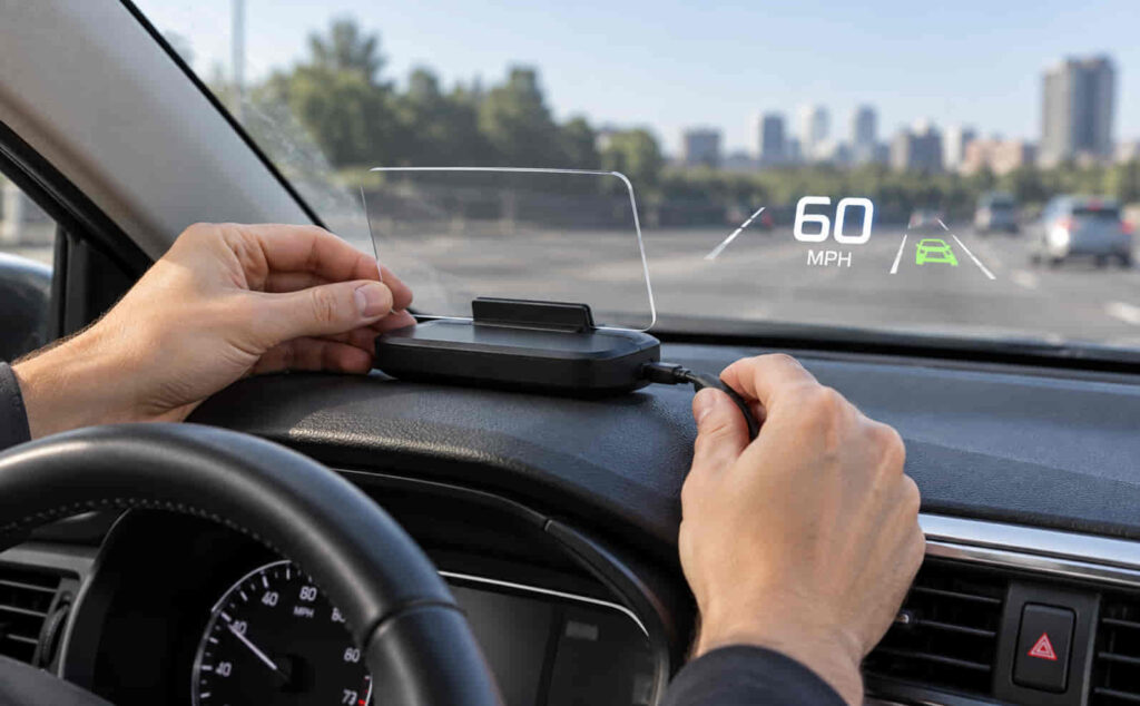
Installing a heads-up display (HUD) in a car involves positioning the display on the dashboard, connecting it to a compatible power or data source, routing the cable, and calibrating the projected information so it is clearly visible from the driver’s seat. Most aftermarket HUDs use either an OBD-II connection to obtain vehicle data or a GPS signal to calculate information such as driving speed. Identifying which type you have is therefore the first step before installation.
An OBD-II HUD normally connects to the vehicle’s OBD-II diagnostic port and can display data such as speed, engine RPM, voltage, and other supported vehicle information. A GPS HUD does not rely on the vehicle’s OBD-II data for speed measurement; it uses satellite positioning and generally requires only a suitable power connection. This difference affects compatibility, cable routing, setup, and troubleshooting.
A typical plug-and-play HUD can be installed without modifying the dashboard or factory wiring. However, correct placement is essential because the projection must remain within the driver’s natural viewing area without obstructing the road. This guide explains how to check HUD compatibility, choose an installation position, connect OBD-II and GPS HUDs, route the cable, calibrate the display, test the installation, and resolve common problems after setup.
What Do You Need to Install a Heads-Up Display in a Car?
To install a heads-up display in a car, you need a compatible HUD unit, its supplied connection cable, a suitable mounting surface, and access to the power or data source required by the device. The exact installation equipment depends primarily on whether the HUD obtains vehicle information through an OBD-II connection or uses GPS to calculate driving data. Checking the HUD type before installation prevents you from searching for a connection that the device does not use.
An OBD-II HUD normally comes with a cable that connects the display directly to the vehicle’s OBD-II diagnostic port. This connection can provide both operating power and access to supported vehicle data, allowing the HUD to display information such as vehicle speed, engine RPM, voltage, coolant temperature, or other parameters available from the vehicle. The specific data displayed depends on the HUD model and the information that the vehicle makes available through its diagnostic system.
A GPS HUD uses a different installation method because it calculates information such as vehicle speed from satellite positioning rather than reading that value through the vehicle’s diagnostic system. Depending on the model, the device may receive power through a USB connection or a 12V accessory socket. This makes GPS HUD installation less dependent on OBD-II compatibility, although the device still needs a stable power source and a position where it can operate correctly.
You should also inspect the mounting accessories supplied with the HUD before placing it on the dashboard. Aftermarket units may use a non-slip pad, adhesive mounting surface, or another manufacturer-specified mounting method. Some windshield-projection HUDs may also use reflective film to improve the visibility of projected information or reduce double reflections. Reflective film should not automatically be installed with every HUD because whether it is required depends on the projection design and the manufacturer’s instructions.
The vehicle owner’s manual and the HUD installation manual are therefore two important references during preparation. The vehicle manual can help identify the diagnostic port and relevant electrical information, while the HUD manual specifies its required connection, mounting method, operating voltage, settings, and supported functions. Confirming these requirements before routing cables makes it easier to determine whether the installation is genuinely plug-and-play or requires additional work.
How Do You Check Whether a HUD Is Compatible With Your Car?
Check HUD compatibility by matching the display’s connection method and supported vehicle requirements with the systems available in your car. An OBD-II connector physically fitting into the diagnostic port does not by itself confirm that every HUD function will work. The display must also be able to communicate with the vehicle in the manner required by that particular HUD model.
For an OBD-II HUD, start by confirming that the vehicle has the required diagnostic connection and that the HUD manufacturer lists the vehicle, protocol, model year, or applicable vehicle category as supported. OBD-II HUDs obtain information from vehicle systems, so available functions can differ between cars. One compatible vehicle may provide speed, RPM, coolant temperature, and voltage data, while another vehicle-HUD combination may provide a smaller set of supported parameters. Manufacturer compatibility information should therefore take priority over assumptions based only on the appearance of the connector.
Compatibility also affects how the HUD behaves when the engine starts and stops. An OBD-II display may be designed to detect vehicle operation and switch itself on or off accordingly. If the HUD and vehicle do not communicate correctly, symptoms can include failure to start, missing vehicle data, incorrect readings, or the display remaining powered after the vehicle has been switched off. Identifying compatibility before permanent mounting makes these problems easier to diagnose because the HUD can first be tested while the cable remains accessible.
A GPS HUD is the practical alternative when the required driving information does not need to come from the vehicle’s OBD-II system. Because vehicle speed can be calculated from GPS data, the HUD does not need to obtain that measurement directly from the engine control or diagnostic system. This reduces its dependence on vehicle-specific data protocols and makes GPS-based displays suitable for a broader range of vehicles when the primary requirement is information such as driving speed.
However, an OBD-II HUD and a GPS HUD should not be treated as functionally identical. A GPS unit can display data it can calculate or obtain independently, but it cannot automatically provide engine parameters that require access to vehicle systems. For example, a GPS HUD may provide speed without accessing the car’s diagnostic data, whereas an OBD-II HUD may also display RPM or supported engine information. The correct choice therefore depends on both vehicle compatibility and the information the driver wants the HUD to display.
Compatibility should be confirmed before the HUD is permanently attached to the dashboard. Connect and temporarily position the unit first, start the vehicle as instructed by the manufacturer, and verify that the expected information appears. Once the display receives the required data and behaves correctly during vehicle startup and shutdown, you can proceed to determine its permanent position and route the cable more cleanly.
Read more: How To Test A Heater Core
Where Should You Install a Heads-Up Display in Your Car?
Install a heads-up display on the dashboard where its projected information is visible within the driver’s natural viewing area without blocking the view of the road. The exact position depends on the HUD design, dashboard shape, windshield angle, driving position, and projection distance specified by the manufacturer. For most aftermarket windshield-projection HUDs, the correct location is near the base of the windshield and aligned with the area the driver can read without significantly shifting attention away from the road.
Choose the position while sitting in your normal driving posture rather than placing the HUD based only on the center of the dashboard. Seat height and distance from the steering wheel change the driver’s viewing angle, so a position that works for one driver may produce a poorly aligned projection for another. Temporarily place the HUD on the dashboard, turn it on, and observe the projected information from the normal driving position before securing the unit. The display should be readable without requiring you to lean forward, move your head substantially, or look away from the normal forward field of view.
The distance between the HUD and windshield also affects where the projected image appears. Moving the unit forward, backward, or sideways can change the apparent position of the information on the glass. A HUD placed too close to an unsuitable section of the windshield may produce a projection that is difficult to read, while incorrect alignment can move part of the display outside the driver’s preferred viewing area. Test the projection first and use the mounting distance recommended for the specific HUD instead of assuming that one dashboard position works for every vehicle.
Windshield construction can also affect projection quality. Some windshield-projection HUDs produce a secondary reflection that appears as a faint duplicate of the main image, commonly described as a double or ghost image. A reflective film may reduce this effect on HUD models designed to use one, but the film should only be added when required or recommended for that display. Installing film unnecessarily can alter the appearance of the windshield without solving a problem that the HUD does not have.
The mounting surface should keep the HUD stable during acceleration, braking, and normal road vibration. Clean the selected dashboard area before applying the supplied mounting pad or adhesive so dust and surface residue do not reduce adhesion. Avoid permanently attaching the unit until its projection, viewing angle, power connection, and cable path have been tested. Temporary positioning makes it possible to correct alignment without repeatedly removing adhesive or mounting material.
Cable routing should also influence the final HUD position. The cable needs a practical path from the display to the OBD-II port, USB power source, or 12V accessory socket without interfering with steering, pedals, vehicle controls, or the driver’s movement. A visually convenient HUD position is not a suitable installation position if its cable must cross an area used to operate the vehicle. Selecting the projection position and cable path together creates a cleaner installation and reduces the need to reposition the HUD later.
How Do You Install an OBD-II Heads-Up Display?
Install an OBD-II heads-up display by locating the vehicle’s OBD-II diagnostic port, connecting the HUD cable, positioning the display on the dashboard, routing the cable securely, and configuring the HUD after the vehicle is started. The process is generally plug-and-play when both the vehicle and HUD are compatible because the supplied OBD-II connection can provide the display with access to supported vehicle information without requiring a separate connection to individual sensors.
Begin with the vehicle stationary and follow the shutdown or ignition-state instructions provided by the HUD manufacturer before making the connection. Locate the OBD-II diagnostic port, which is generally positioned within reach of the driver’s seating area and is commonly found beneath the dashboard on the driver’s side. Its exact location varies by vehicle, so use the vehicle owner’s manual when the connector is not immediately visible. Identifying the correct diagnostic connector is preferable to removing dashboard panels or connecting the HUD to an unfamiliar electrical socket.
Connect the HUD’s supplied OBD-II plug firmly to the vehicle’s diagnostic port without forcing the connector. The plug is designed to fit in a specific orientation, and excessive pressure should not be necessary when it is correctly aligned. Connect the other end to the HUD if the cable is detachable, then leave the display temporarily positioned on the dashboard. At this stage, the objective is to confirm operation before hiding the cable or permanently securing the device.
Start the vehicle according to the HUD manufacturer’s instructions and allow the display to initialize. A compatible OBD-II HUD should establish communication with the vehicle and begin showing the parameters supported by the device and vehicle combination. Depending on the model, these parameters can include vehicle speed, engine RPM, system voltage, coolant temperature, or other available diagnostic information. The presence of an OBD-II connection does not mean every vehicle will expose the same set of data, so confirm the expected functions against the HUD documentation.
Check the displayed information before continuing with permanent installation. Vehicle speed should respond as expected when the car is driven safely, engine RPM should change with engine operation when that parameter is supported, and other readings should remain plausible for the vehicle’s operating state. A display that powers on but shows missing or implausible information may have a communication, configuration, or compatibility issue. Resolve that problem before concealing the cable because access to the connector may be required during troubleshooting.
Once communication has been confirmed, route the cable from the OBD-II port toward the selected HUD position. Keep the cable away from the pedals, steering components, control levers, and any area where it could interfere with normal vehicle operation. Where the vehicle design and HUD instructions allow it, the cable can follow the edge of the dashboard or suitable trim so that unnecessary loose sections are not left around the driver’s footwell. Do not force wiring into components or locations that the vehicle or HUD manufacturer identifies as restricted.
Secure the HUD only after the cable reaches the display without pulling on either connector. The unit should remain in the projection position established during the earlier placement test. A cable under continuous tension can move a lightweight HUD out of alignment and place unnecessary force on its connectors, while excess loose cable can make the installation untidy or interfere with the driver’s area. The finished connection should therefore keep both the display and cable stable without changing the intended projection angle.
After the physical installation is complete, configure the HUD according to the data you want to monitor. Set the required measurement units and check display settings such as brightness, warning thresholds, or speed correction when those functions are available. Calibration becomes particularly important when the displayed speed does not correspond with the reference used for the vehicle. The adjustment method varies between HUD models, so correction values should be entered through the device’s documented calibration settings rather than estimated by changing unrelated parameters.
Finally, test both startup and shutdown behavior. The HUD should activate according to its intended operating method when the vehicle is started and should shut down as designed after the vehicle is turned off. Some devices use a shutdown delay or vehicle-voltage detection rather than switching off at the exact moment the ignition is turned off. If the HUD remains powered beyond its documented behavior, check its settings and vehicle compatibility before assuming the installation is complete. This final test is important because correct installation includes both reliable data communication while driving and appropriate power behavior when the vehicle is no longer operating.
How Do You Install a GPS Heads-Up Display?
Install a GPS heads-up display by positioning the unit on the dashboard, connecting it to its specified power source, routing the power cable securely, acquiring a GPS signal, and checking the displayed speed before driving normally. Unlike an OBD-II HUD, a GPS HUD does not need to obtain vehicle speed from the car’s diagnostic system. It calculates speed from satellite positioning, which changes both the connection process and the type of information the device can display.
Start by temporarily positioning the GPS HUD on the dashboard in the projection area selected earlier. The display should remain within the driver’s natural viewing area without obstructing the road ahead. Do not permanently attach the unit at this stage because its final position may need adjustment after the display is powered on. Windshield angle, dashboard height, seat position, and the HUD’s projection angle can all change where the information appears from the driver’s perspective.
Connect the HUD to the power source specified by its manufacturer. Depending on the model, an aftermarket GPS HUD may use USB power or a 12V accessory connection. The correct connection is determined by the device’s electrical requirements rather than by the fact that it uses GPS. Use the supplied cable and specified power source because an incompatible power connection can prevent normal startup or cause unstable operation.
After connecting the power, route the cable so that it does not cross the steering controls, pedals, gear selector, or other areas required for vehicle operation. The cable should reach the HUD without being stretched and should not leave excessive loose wiring around the driver’s area. Once the device position and cable path have been confirmed, secure the HUD using the mounting method supplied or recommended by the manufacturer.
Turn on the GPS HUD and allow it to establish a satellite signal. GPS acquisition is necessary because the device needs positioning data before it can calculate vehicle speed. Signal acquisition can be affected by the operating environment, so initial testing should be performed where the device has suitable satellite reception rather than in a location where the signal may be obstructed. A GPS HUD that has power but has not established positioning should not automatically be treated as an incorrectly installed device.
The main installation difference between GPS and OBD-II HUDs is the source of driving data. An OBD-II HUD communicates with compatible vehicle systems and may display parameters such as speed, RPM, voltage, or coolant temperature when those values are supported. A GPS HUD can determine speed independently of the vehicle’s diagnostic data but cannot obtain engine-specific parameters merely through its GPS connection. This makes a GPS HUD useful when the primary requirement is a projected speed display and OBD-II communication is unavailable or unnecessary.
Complete the installation by checking the GPS speed reading during normal vehicle movement in a safe environment. The displayed value should update as vehicle speed changes rather than remaining fixed or responding abnormally. If the HUD consistently differs from the reference speed used for setup, check whether the device provides a speed correction or calibration setting. Correct the reading through that setting instead of changing the physical installation unless poor GPS reception is causing the problem.
How Do You Set Up a HUD After Installing It?
Set up a heads-up display after installation by configuring its measurement units, display brightness, projection position, supported vehicle data, warning values, and speed calibration where these settings are available. Physical installation only establishes the device’s position and connection. Configuration determines whether the projected information is accurate, readable, and appropriate for the driver’s requirements.
Start with the measurement units because they affect the interpretation of the displayed data. Configure vehicle speed in the unit appropriate for the intended use, such as mph or km/h, and verify other supported units according to the HUD manual. An incorrect unit setting can make a correctly functioning device appear inaccurate, particularly when comparing its speed value with the vehicle’s existing instruments.
Next, adjust the projection position from the driver’s normal seating position. The important information should remain visible without requiring a substantial change in head position. Reposition the physical HUD if the projection sits too high, too low, or outside the preferred viewing area. Where the device provides a display orientation or projection adjustment, use that setting to refine the image after the physical position has been established. The objective is a stable display that can be read while maintaining normal forward attention.
Brightness should provide enough contrast for the information to remain readable without making the projection unnecessarily distracting. Some HUDs provide automatic brightness control, while others require manual adjustment. Check the display under the lighting conditions in which the vehicle is normally used because a brightness level suitable for daylight may be excessive after dark. If the HUD provides separate brightness levels or automatic adjustment, configure them before considering the display setup complete.
Speed calibration should be performed when the HUD provides a persistent difference from the reference value used for comparison. Many aftermarket units include a correction parameter that changes the displayed speed by a specified ratio or offset. Use the calibration procedure documented for the specific model because adjustment systems are not standardized across all HUDs. A correction value designed for one device should not be assumed to apply to another.
GPS and OBD-II HUDs can require calibration for different reasons. A GPS HUD calculates movement from satellite positioning, whereas an OBD-II HUD displays speed information obtained through its communication with the vehicle. If a GPS HUD produces irregular rather than consistently offset readings, GPS reception should be checked before applying a correction. If an OBD-II HUD displays unexpected data, compatibility and communication should also be checked because calibration cannot repair a parameter that the device is reading incorrectly.
Configure additional vehicle information only when it is supported by both the HUD and the relevant data source. An OBD-II HUD may offer parameters such as RPM, voltage, or coolant temperature, while a basic GPS HUD may focus primarily on speed and GPS-derived information. Showing every available parameter is not necessary for a successful installation. The display should prioritize information that can be read clearly without overcrowding the projection area.
Warning thresholds should also be configured according to the functions documented for the device. Some HUDs provide alerts associated with parameters such as speed or other supported vehicle information. These thresholds are settings rather than universal values, so they should be selected according to the HUD documentation, applicable vehicle information, and the driver’s intended use instead of copying arbitrary settings from another HUD installation.
Finish the setup by switching the vehicle off and starting it again. This confirms whether the HUD retains its configuration and whether its startup and shutdown behavior works as intended. Recheck measurement units, brightness, projection position, and the primary displayed information after restart. A HUD is correctly set up when it powers and shuts down as designed, retains the required configuration, displays the expected information consistently, and remains readable from the driver’s normal seating position.
How Do You Test a Heads-Up Display After Installation?
Test a heads-up display after installation by checking its startup and shutdown behavior, displayed data, projection position, brightness, connection stability, and cable security under normal vehicle operation. A HUD that turns on is not necessarily installed correctly. The installation is complete only when the device receives the expected data, remains readable from the driver’s normal position, stays securely mounted, and operates correctly when the vehicle is started and switched off.
Begin the test with the vehicle stationary. Start the vehicle according to the HUD manufacturer’s instructions and observe how the display initializes. An OBD-II HUD should establish communication with the compatible vehicle systems, while a GPS HUD should power on and begin acquiring the positioning signal required for GPS-derived information. An unusually long startup, missing data, repeated restarts, or failure to establish the required connection indicates that the power source, connection, configuration, or compatibility should be checked before road testing.
Check each displayed parameter that you intend to use. For an OBD-II HUD, this may include speed, engine RPM, voltage, coolant temperature, or other supported vehicle information. The available parameters depend on both the HUD and vehicle. A GPS HUD should be checked primarily for the information it derives independently, such as vehicle speed. The objective is not to activate every function available in the HUD menu but to confirm that the information selected for regular use responds consistently.
The projected image should then be checked from the driver’s normal seating position. Numbers and symbols should remain visible without requiring the driver to lean toward the windshield or substantially change head position. If the image is outside the intended viewing area, reposition the HUD before treating the installation as permanent. Physical positioning should be corrected before relying on software settings to compensate for a poorly placed unit.
Test brightness under different ambient lighting when practical. The display needs enough contrast to remain readable during daylight but should not be excessively bright in darker conditions. A HUD with automatic brightness adjustment should respond appropriately as surrounding light changes. A manually controlled display should be set to a level that maintains readability without making the projected information unnecessarily dominant in the driver’s field of view.
A controlled road test can then confirm whether speed and other dynamic values respond as expected while the vehicle moves. If the HUD speed remains consistently different from the reference used for comparison, use the device’s documented calibration function when available. A stable offset is different from a reading that repeatedly jumps, disappears, or changes unpredictably. Irregular GPS readings can indicate positioning or signal problems, while missing OBD-II information can indicate communication or compatibility problems rather than a simple calibration error.
Check the physical installation again after the road test. The HUD should remain in its original position during acceleration, braking, turning, and normal road vibration. The power or data cable should also remain secure without pulling on the HUD or moving into the driver’s operating area. A device that functions electronically but shifts on the dashboard has not been mounted correctly.
Finish the test by switching the vehicle off and observing the HUD. The display should follow the shutdown behavior specified for its model. Some units may not switch off at the exact moment the ignition is turned off because their operating logic can include delayed shutdown or voltage detection. A HUD that remains powered outside its documented behavior requires further investigation because persistent power can indicate an incorrect setting, unsuitable connection method, or compatibility issue.
Do You Need Reflective Film for a Heads-Up Display?
A heads-up display needs reflective film only when its projection design or manufacturer instructions require the film to improve image visibility or control unwanted reflections. Reflective film is not a universal requirement for aftermarket HUD installation, and it should not automatically be applied to every windshield-projection display.
A windshield-projection HUD works by directing light toward the windshield so the driver sees the reflected information. The optical characteristics of the windshield influence how that projection appears. Depending on the combination of windshield construction, viewing angle, ambient light, and HUD design, the projected image may already be sufficiently clear without additional material. In that situation, adding reflective film provides no necessary installation benefit.
When a compatible HUD requires reflective film, its position should correspond to the actual projection area rather than an estimated location on the windshield. Establish the HUD’s final dashboard position first and turn the display on to identify where the image appears from the driver’s normal seating position. The film can then be aligned with that projection area according to the product instructions. Installing the film before determining the HUD position increases the risk that the projected information will not align correctly with the treated section of glass.
The windshield surface should be prepared according to the film manufacturer’s installation instructions before application. Dust, residue, bubbles, or incorrect alignment can affect the appearance of the projection. The film should also be compatible with the HUD rather than treated as a generic solution for every visibility problem. Poor brightness, an incorrect projection angle, or an unsuitable HUD position should be corrected at their source instead of automatically being attributed to the absence of reflective film.
Reflective film can be particularly relevant when the driver sees a double or ghost image. HUD ghosting occurs when the projected light creates more than one visible reflection, causing a secondary version of the displayed numbers or symbols to appear beside the primary image. This effect can reduce readability because the driver sees overlapping information instead of one clearly defined projection.
The windshield itself can contribute to this effect because automotive glass is constructed from multiple layers and reflective surfaces. Light projected toward the glass can therefore produce reflections that are slightly displaced from each other from the driver’s viewing angle. The severity of the duplicate image depends on factors such as windshield construction, HUD position, projection angle, and the optical design of the display.
Before adding film to address ghosting, adjust the HUD position and viewing angle within the limits specified for the device. A change in placement can alter how the projected light reaches the windshield and may improve image alignment. If the manufacturer provides reflective film specifically for the HUD and recommends it for reducing double images, install it only after the final projection position has been established.
A clear HUD projection therefore depends on the complete optical setup rather than reflective film alone. Correct dashboard placement, suitable viewing angle, appropriate brightness, windshield characteristics, and the HUD’s projection design all contribute to image quality. Reflective film is one installation component for compatible displays, not a substitute for correct positioning and calibration.
Why Is the Heads-Up Display Not Working After Installation?
A heads-up display that does not work after installation usually requires checking its power source, cable connection, vehicle compatibility, data connection, and device settings before changing the installation itself. The correct troubleshooting sequence depends on whether the device is an OBD-II HUD or a GPS HUD because the two types receive driving information differently. Separating power problems from data problems makes it easier to identify the actual cause.
If the HUD does not turn on at all, check the power path first. Confirm that the supplied cable is fully connected at both ends and that the device is connected to the power source specified by its manufacturer. An OBD-II HUD may receive operating power through its diagnostic connection, while a GPS HUD may use USB or a 12V accessory connection. A loose connector, unsuitable power source, damaged cable, or incorrect vehicle ignition state can prevent the display from starting even when the HUD itself is functional.
An OBD-II HUD that powers on but does not show the expected vehicle information presents a different problem. In this situation, electrical power is reaching the display, but communication with the vehicle may not be working as required. Confirm that the HUD is compatible with the vehicle and that the expected parameters are supported by that vehicle-HUD combination. A physical OBD-II connection does not guarantee access to every parameter the HUD is capable of displaying.
For example, the display may turn on normally while engine RPM, coolant temperature, or another vehicle parameter remains unavailable. This does not necessarily mean that the mounting or power connection is incorrect. The problem can result from the data required by the HUD not being available through the expected communication method. Compatibility should therefore be checked before repeatedly reconnecting the device or changing unrelated display settings.
A GPS HUD that powers on but does not display speed correctly should be checked for GPS acquisition before calibration. The unit requires suitable positioning data to calculate vehicle speed, so testing in an environment with poor satellite reception can produce missing or unstable information. Move the vehicle to an appropriate testing environment and allow the HUD to establish its GPS connection before deciding that the device is inaccurate.
A HUD that consistently shows the wrong speed should be calibrated only after its data source is working correctly. A stable difference between the HUD reading and the reference speed can often be addressed through the speed correction function provided by the device. Follow the manufacturer’s calibration procedure because HUD models use different adjustment methods and correction values.
Calibration should not be used to hide an unstable reading. If the displayed speed jumps unpredictably, repeatedly disappears, or changes without corresponding vehicle movement, identify the underlying GPS or OBD-II data problem first. Calibration changes a consistent measurement offset; it does not repair interrupted communication or poor signal acquisition.
Another installation problem occurs when the HUD remains on after the vehicle is switched off. This behavior does not automatically indicate a fault because some HUDs use delayed shutdown, voltage detection, or other power-management logic. Check the manufacturer’s specified shutdown behavior and wait for the documented period before changing the connection.
If an OBD-II HUD continues operating beyond its expected shutdown behavior, check its power settings and vehicle compatibility. Some vehicle electrical systems may continue supplying power at the diagnostic connector after the engine or ignition has been switched off. A HUD that relies on voltage or communication changes to determine when the vehicle has stopped may therefore behave differently between vehicle models.
Persistent operation also raises the question of battery drain. A HUD can contribute to battery discharge if it continues drawing power while the vehicle is parked, although the practical effect depends on the device’s power consumption, connection behavior, parking duration, and vehicle battery condition. For this reason, a newly installed HUD should be observed after the first several shutdown cycles rather than assuming that a lit display will eventually switch off.
Do not modify factory wiring solely to solve a shutdown problem unless the HUD is designed for that installation method and the work can be completed appropriately. A plug-and-play device that does not shut down correctly should first be checked against its manual, settings, connection requirements, and vehicle compatibility. Electrical modifications introduce a different installation scope from connecting a standard OBD-II, USB, or 12V aftermarket HUD.
Physical installation should also be inspected when the display works intermittently. A cable routed under tension can partially loosen at the HUD or power source as the vehicle moves, while an unsecured connector can produce intermittent power or data communication. Check that both ends of the cable remain fully seated and that cable routing does not place continuous force on either connector.
Troubleshooting is complete when the HUD starts reliably, receives its intended information, maintains stable readings, retains its configuration, and shuts down according to its designed behavior. If these conditions cannot be achieved after verifying the connection, settings, and stated compatibility, the device or vehicle-HUD combination requires further diagnosis rather than additional display calibration.
Can You Install a Heads-Up Display in Any Car?
You can install an aftermarket heads-up display in many cars, but not every HUD is compatible with every vehicle. Compatibility depends primarily on the type of HUD, its power and data requirements, the vehicle’s available connections, and the information the display is designed to show. A GPS HUD generally has fewer vehicle-specific data requirements than an OBD-II HUD because it can calculate speed without communicating directly with the vehicle’s diagnostic system.
An OBD-II HUD requires more than physical access to an OBD-II connector. The device must communicate correctly with the vehicle to obtain the parameters it is designed to display. Two cars with physically similar diagnostic ports can therefore provide different results with the same HUD. One vehicle-HUD combination may support speed, RPM, voltage, and coolant information, while another may provide fewer usable parameters or fail to communicate as required.
A GPS HUD reduces this dependency because its primary driving information can come from satellite positioning. If the device only needs a compatible electrical supply and GPS reception to provide speed information, it can work without reading vehicle speed through the diagnostic system. This makes GPS-based models an option when OBD-II compatibility is unavailable or when the driver only requires information that the HUD can determine independently.
The physical interior of the car also affects whether a particular HUD can be installed effectively. The dashboard needs a suitable location for the unit, and a windshield-projection HUD needs an appropriate projection area that remains visible from the driver’s normal seating position. Dashboard shape, windshield angle, mounting stability, and cable routing can therefore influence practical compatibility even when the electronic connection works correctly.
An aftermarket dashboard HUD should also be distinguished from a factory-style HUD retrofit. A plug-and-play OBD-II or GPS display is a separate accessory designed to add projected information with relatively limited vehicle integration. Retrofitting a factory-style system can involve vehicle-specific displays, dashboard components, wiring, windshields, control modules, coding, or other integrated components. The installation requirements described for a plug-and-play aftermarket HUD should not automatically be applied to a factory retrofit.
The most reliable way to determine compatibility is therefore to check the requirements of the specific HUD against the specific vehicle before permanent installation. Confirm the connection method and manufacturer-stated compatibility, then test power, data acquisition, projection, startup, and shutdown behavior before securing the device and concealing its cable.
How Long Does It Take to Install a Heads-Up Display?
Installing a basic aftermarket heads-up display can be a relatively short process when the device uses a plug-and-play connection, while installations involving cable concealment, reflective film, troubleshooting, or vehicle integration require additional time. There is no single installation time that applies to every HUD because the connection method and desired finish determine how much work is required.
A simple GPS HUD generally involves selecting a dashboard position, connecting the specified power cable, acquiring a GPS signal, and configuring the display. An OBD-II HUD adds the need to locate the diagnostic port, confirm communication with the vehicle, and route the OBD-II cable from the port to the dashboard. Both installations remain relatively straightforward when the supplied cables reach their connection points easily and no interior components need to be removed.
Cable management can account for a significant part of the installation process. A HUD may function within minutes of being connected, but a finished installation also requires the cable to remain away from pedals, steering controls, and other operating areas. Testing several dashboard positions before securing the unit can add time but reduces the likelihood of having to remove and reinstall it because of poor projection alignment.
Reflective film can add another stage when the HUD is designed to use it. The projection area should first be established from the driver’s normal seating position before the film is aligned with the windshield. Similarly, speed calibration and brightness adjustment should be completed after the device has established a reliable power and data connection. Skipping these steps makes the initial installation faster but does not mean the HUD has been fully set up.
Troubleshooting creates the greatest variation in installation time for plug-and-play units. A compatible HUD that immediately receives power and the expected data can move quickly from connection to calibration. A device that does not start, cannot communicate with the vehicle, receives an unstable GPS signal, or fails to shut down correctly requires diagnosis before the installation can be considered complete.
Installation time should therefore be measured by successful setup rather than by how quickly the HUD can be plugged in. The process is complete when the unit is securely positioned, the cable is safely routed, the intended information is stable, the projection is readable, the settings are calibrated, and startup and shutdown behavior have been verified.
Should You Install a HUD Yourself or Have It Professionally Installed?
You can install a plug-and-play aftermarket HUD yourself when the device only requires a manufacturer-specified OBD-II, USB, or 12V connection and can be mounted without modifying the vehicle’s electrical system. Professional installation becomes more appropriate when the work requires electrical wiring changes, significant interior trim removal, vehicle-specific integration, or a factory-style HUD retrofit.
A typical OBD-II HUD is designed around a relatively simple connection. Once compatibility has been confirmed, the installation primarily involves connecting the supplied cable, positioning the display, safely routing the cable, and configuring the device. A GPS HUD can be similarly straightforward when it only needs its specified power source. These installation methods generally do not require the installer to splice factory wiring or modify electronic control systems.
DIY installation still requires attention to the physical placement of both the HUD and its cable. The display must not obstruct the driver’s view, and wiring should not interfere with pedals, steering components, controls, or normal entry and exit from the vehicle. The fact that a device is plug-and-play describes its electrical connection; it does not eliminate the need for correct positioning and safe cable management.
Professional installation is more relevant when achieving the desired result requires work beyond the HUD manufacturer’s normal plug-and-play procedure. Examples include integrating components into the dashboard, making permanent electrical connections, removing interior panels beyond what the installer can safely handle, or retrofitting equipment designed around vehicle-specific electronics. These tasks require a different level of installation knowledge from placing an aftermarket display on the dashboard.
A professional may also be useful when a supposedly compatible HUD repeatedly develops unresolved electrical or communication problems. Persistent power after shutdown, unreliable OBD-II communication, or installation requirements involving vehicle wiring should be diagnosed rather than addressed through experimental electrical modifications. Changing factory wiring without establishing the cause can introduce problems unrelated to the original HUD installation.
The decision therefore depends on installation complexity rather than on the HUD category alone. A compatible plug-and-play unit with an accessible connection and straightforward cable route is suited to DIY installation when the manufacturer’s instructions can be followed correctly. An installation involving permanent wiring, extensive trim work, or integration with factory vehicle systems is better treated as professional automotive electronics work.