Ford ignition switch wiring color codes identify the electrical circuits that control vehicle starting, ignition power, and accessory functions. The ignition switch connects the vehicle battery power supply with essential systems such as the starter motor, ignition components, and electrical accessories. Understanding the wire colors and their functions helps vehicle owners and technicians diagnose starting problems, replace ignition components, and repair wiring connections correctly.
The Ford ignition switch wiring color code is not identical across every vehicle model and production year. Ford vehicles such as the F Series trucks, Mustang, Ranger, and Explorer can use different wiring configurations depending on the electrical system design. Because of these differences, identifying the wire function is more important than relying only on color.
This guide explains the main Ford ignition switch wires, including battery power, ignition, starter, and accessory circuits. It also explains how to read Ford wiring diagrams, test ignition switch wires with a multimeter, and identify common wiring problems. By understanding how the ignition switch wiring system works, you can perform safer electrical troubleshooting and avoid incorrect wire connections.
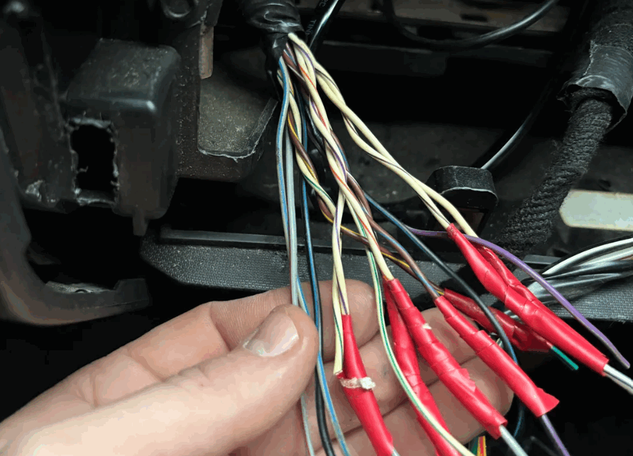
What Are the Ford Ignition Switch Wiring Color Codes?
Ford ignition switch wiring color codes identify the purpose of each wire connected to the ignition switch and show how electrical power moves through the vehicle starting system. These wire colors represent different circuits, including constant battery power, ignition power, starter activation, and accessory operation. The exact colors depend on the Ford model, manufacturing year, engine configuration, and wiring design, so the wire function should always be confirmed with a vehicle specific wiring diagram.
The ignition switch works as a control point between the battery and several electrical systems. When the key or ignition button changes position, the switch routes electrical current to different circuits based on the selected mode. The OFF position disconnects most electrical systems, the ON position activates ignition related circuits, and the START position sends power to the starter circuit to crank the engine.
Ford ignition switch wiring commonly includes four main circuit functions. The battery power wire provides continuous voltage from the battery to the ignition switch. The ignition wire supplies power to engine control and ignition related components when the switch is turned on. The starter wire sends a signal to activate the starter relay or starter motor during engine cranking. The accessory wire powers systems such as the radio, climate controls, and other electrical components when the ignition switch is in the accessory position.
Understanding these wire functions is more important than memorizing a single color pattern because Ford has changed wiring layouts across different vehicle generations. For example, the ignition switch wiring on a Ford F 150 from one production period may not match the wiring configuration used on a Ford Mustang or Ranger from another year. A correct diagnosis requires matching the wire color, terminal position, and circuit purpose together.
What Are the Ford Ignition Switch Wiring Color Codes?
Ford ignition switch wiring color codes identify the electrical purpose of each wire connected to the ignition switch. These codes help technicians and vehicle owners understand which wires provide battery power, activate ignition circuits, control the starter system, and operate electrical accessories. The ignition switch acts as a central control point that distributes electrical current from the battery to different vehicle systems based on the selected ignition position.
The most important ignition switch circuits include the battery power circuit, ignition circuit, starter circuit, and accessory circuit. The battery power wire provides constant voltage from the battery to the ignition switch. The ignition wire supplies power to systems required for engine operation when the key is turned to the ON position. The starter wire sends a temporary signal during engine cranking, while the accessory wire powers electrical features that do not require engine operation.
Ford does not use one universal ignition switch wire color pattern for every vehicle. The wiring configuration changes according to the vehicle model, production year, engine option, and electrical system design. For example, a Ford F 150 wiring system may use different wire colors and connector layouts compared with a Ford Mustang or Ford Ranger from another generation.
Because of these variations, identifying the circuit function is more reliable than depending only on wire color. A correct diagnosis requires checking the wire color, connector position, terminal label, and vehicle specific wiring diagram together. This approach prevents incorrect connections that can damage electrical components or create starting system problems.
Understanding Ford ignition switch wiring color codes provides the foundation for troubleshooting ignition problems, replacing switches, and repairing electrical connections safely.
What Do the Main Ford Ignition Switch Wires Control?
The main Ford ignition switch wires control how electrical power moves through the vehicle. These wires connect the battery, ignition system, starter system, and accessories. Each wire has a specific function. Correct identification helps technicians diagnose electrical problems faster and avoid incorrect connections.
The battery power wire provides constant voltage to the ignition switch. It receives electrical power directly from the battery. This power is available even when the vehicle is turned off. When the ignition switch changes position, it sends this power to other circuits. A damaged battery wire can stop the ignition system from receiving power.
The ignition wire supplies electricity when the ignition switch moves to the ON position. This circuit powers important engine systems. These systems include the engine control module, fuel system components, and ignition components. If this wire fails, the vehicle may have electrical power but the engine may not operate correctly.
The starter wire controls the engine cranking process. It sends a signal when the key moves to the START position. This signal activates the starter relay or starter solenoid. The starter motor then turns the engine until it starts. A problem with this circuit often causes a no crank condition.
The accessory wire powers electrical features that do not require engine operation. These features include the radio, climate control, and dashboard electronics. The accessory circuit works separately from the ignition circuit. This design prevents unnecessary power use during engine starting.
Understanding these four circuits makes Ford ignition switch troubleshooting more accurate. Instead of only checking wire colors, technicians should confirm the wire function with a wiring diagram and voltage test. This method reduces repair mistakes because Ford wiring layouts vary between different models and years.
How Do You Read a Ford Ignition Switch Wiring Diagram?
A Ford ignition switch wiring diagram shows how electrical power moves between the battery, ignition switch, starter system, and vehicle components. The diagram uses symbols, labels, and wire paths to represent the physical wiring structure. Reading this information correctly helps identify power sources, circuit connections, and possible electrical failures.
The first step is understanding the main symbols in the diagram. Wiring diagrams usually show components such as the ignition switch, battery, fuse, relay, and electrical connectors. Each component has a specific symbol and label. These labels help technicians locate the correct part in the vehicle and understand how the circuit operates.
Wire labels provide important information about electrical connections. A diagram may identify wires by color, connector position, or terminal number. For example, a wire label can show where a power source enters the ignition switch and where that power leaves toward another component. This information is useful when testing voltage or repairing damaged wiring.
The ignition switch diagram also shows the relationship between different circuits. Battery power enters the switch first. The switch then distributes voltage to the ignition, starter, and accessory circuits depending on the key position. This electrical flow explains why a failure in one wire can affect specific vehicle functions while leaving other systems working.
To find the correct Ford ignition switch wiring diagram, vehicle information must match the diagram source. Important details include the model year, vehicle model, engine type, and trim level. A Ford F 150 from one year may have a different wiring layout from a Ford Mustang or Ford Ranger. Using the wrong diagram can lead to incorrect testing and wiring mistakes.
A proper wiring diagram does more than show wire colors. It explains the complete electrical relationship between components. This makes it an essential tool for ignition switch replacement, troubleshooting, and electrical repairs.
How Do You Test Ford Ignition Switch Wiring With a Multimeter?
Testing Ford ignition switch wiring with a multimeter helps identify electrical problems before replacing components. A multimeter can measure voltage, continuity, and electrical flow through the ignition circuit. This process helps determine whether the issue comes from the ignition switch, wiring connection, fuse system, or another starting system component.
The first step is preparing the vehicle for testing. Turn off the ignition and disconnect the battery if required for safety. Then locate the ignition switch connector and identify the correct terminals using a Ford wiring diagram. The diagram helps match each wire to its circuit function, including battery power, ignition output, starter signal, and accessory power.
The battery power wire should be tested first because it provides the main voltage source for the ignition switch. A functioning battery wire should show continuous voltage even when the ignition is turned off. If no voltage is detected, the problem may exist in the battery connection, fuse, wiring harness, or power supply circuit.
The ignition wire should receive voltage when the key is turned to the ON position. The starter wire should only receive voltage during the START position. The accessory wire should provide power when the ignition switch is placed in the accessory mode. These different voltage conditions confirm whether the ignition switch is distributing power correctly.
A faulty Ford ignition switch can create several symptoms. Common signs include no crank conditions, intermittent starting problems, loss of accessory power, and unexpected electrical interruptions. For example, a vehicle may have working dashboard lights but fail to activate the starter because the starter signal circuit is not receiving power.
Using a multimeter with a wiring diagram creates a more accurate diagnostic process. It prevents unnecessary parts replacement because the exact failed circuit can be identified before repairs begin.
Why Do Ford Ignition Switch Wire Colors Change by Model and Year?
Ford ignition switch wire colors change between models and production years because vehicle electrical systems continue to evolve. The company updates wiring layouts to support new engine technology, safety systems, electronic modules, and vehicle features. A wire color used for one circuit on an older Ford model may have a different purpose on a newer vehicle.
Changes in electrical architecture are one major reason for these differences. Older Ford vehicles often use simpler ignition systems. The ignition switch may connect directly to several electrical components. Newer vehicles usually include control modules, relays, and network communication systems. These additions create more complex wiring structures.
Different Ford models also require different electrical designs. A Ford F 150 may include circuits for truck specific features and heavy duty components. A Ford Mustang may use another wiring configuration because of performance systems and security technology. Other models, such as the Ford Ranger or Explorer, can have different connectors and wire arrangements depending on their generation.
Model year changes can also affect ignition switch wiring. Manufacturers often update electrical systems during vehicle redesigns or production improvements. Two vehicles with the same model name may use different ignition switch connectors if they belong to different generations.
A universal Ford ignition switch wiring color chart is therefore not always reliable. The correct identification process requires checking the vehicle model, production year, engine type, and trim level. A vehicle specific wiring diagram provides the most accurate information about wire colors, terminal positions, and circuit functions.
Using the correct wiring information improves diagnostic accuracy. It helps technicians avoid incorrect connections and reduces the risk of electrical damage during ignition switch repairs.
What Are the Common Ford Ignition Switch Wiring Problems?
Ford ignition switch wiring problems usually occur because of damaged wires, poor electrical connections, worn components, or incorrect repairs. The ignition switch system controls several important circuits, so a small wiring issue can affect starting performance, accessory operation, or engine power. Identifying the exact cause helps prevent unnecessary replacement of working components.
One common problem is a damaged ignition switch connector. The connector transfers electrical power between the wiring harness and the ignition switch. Heat, vibration, and repeated use can weaken the connector terminals over time. Loose terminals may create intermittent electrical contact. This can cause symptoms such as random starting failures or accessories that stop working unexpectedly.
Corrosion is another frequent cause of ignition switch wiring failure. Moisture can enter electrical connectors and create resistance between terminals. Increased resistance reduces electrical flow and can interrupt power delivery to important circuits. A corroded connection may allow some systems to work while preventing others from receiving enough voltage.
Incorrect wiring during ignition switch replacement can also create electrical problems. Connecting a wire to the wrong terminal may reverse circuit functions or prevent the starter and ignition systems from operating correctly. This is why a vehicle specific wiring diagram should always be used during repairs.
A damaged wiring harness can create similar symptoms. Wires located near moving parts or heat sources may become broken, melted, or exposed. These conditions can interrupt electrical signals between the ignition switch and connected components.
Common Ford ignition switch wiring problems often produce recognizable symptoms. These include no crank conditions, intermittent engine starting, loss of accessory power, and electrical systems that operate inconsistently. Proper diagnosis requires checking wire condition, connector quality, voltage readings, and circuit continuity before replacing parts.
A systematic testing approach improves repair accuracy. Inspecting the wiring first can reveal simple issues before more expensive components are replaced.
How Can You Replace or Repair Ford Ignition Switch Wiring?
Replacing or repairing Ford ignition switch wiring requires careful identification of each circuit before making any connection changes. The ignition switch controls important electrical functions, including engine starting, ignition power, and vehicle accessories. Incorrect wiring can create starting failures, electrical shorts, or damage to connected components.
The first step is preparing the vehicle safely. Disconnecting the battery prevents accidental electrical contact during the repair process. After removing power, inspect the ignition switch connector and wiring harness for visible damage. Look for signs of melted insulation, broken wires, loose terminals, or corrosion around the connector pins.
The next step is identifying each wire according to the correct Ford wiring diagram. The battery power wire, ignition wire, starter wire, and accessory wire must be matched with their correct terminals. Wire color alone should not be the only reference because Ford uses different wiring configurations across models and years.
When replacing an ignition switch connector, damaged terminals should be repaired or replaced instead of forcing a poor connection. A secure electrical connection allows proper current flow and reduces the chance of future failures. If the wiring harness has damaged sections, the affected area should be repaired with suitable automotive wiring methods.
After completing the repair, the ignition system should be tested before normal vehicle operation. Check that the vehicle receives battery power, the ignition circuit activates correctly, and the starter circuit functions when the key moves to the START position. Testing each circuit confirms that the repair restored the correct electrical flow.
A proper repair process focuses on accuracy rather than speed. Using the correct wiring diagram, verifying each terminal, and testing the system afterward helps maintain the reliability of the Ford ignition switch wiring system.
Conclusion
Ford ignition switch wiring color codes help identify the electrical circuits responsible for vehicle starting, ignition operation, and accessory power. Understanding these wire functions makes troubleshooting more accurate because each circuit has a specific role within the vehicle electrical system.
The battery power wire supplies the ignition switch with continuous voltage. The ignition wire activates engine related electrical systems. The starter wire controls the engine cranking signal. The accessory wire powers additional electrical features. Identifying these circuits correctly is essential when diagnosing ignition problems or replacing wiring components.
Ford wiring systems vary between models and production years. A Ford F 150, Mustang, Ranger, or Explorer may use different wire colors and connector layouts depending on its electrical design. For this reason, technicians should always confirm wire functions with a vehicle specific wiring diagram instead of relying only on general color charts.
Accurate testing and proper identification reduce the risk of wiring mistakes. Using a multimeter, checking connector conditions, and verifying circuit functions provide a reliable repair process. These steps help maintain the performance and safety of the Ford ignition switch wiring system.
For further electrical troubleshooting, related topics such as Ford starter wiring systems and automotive electrical testing methods can provide additional guidance for diagnosing starting and power distribution problems.