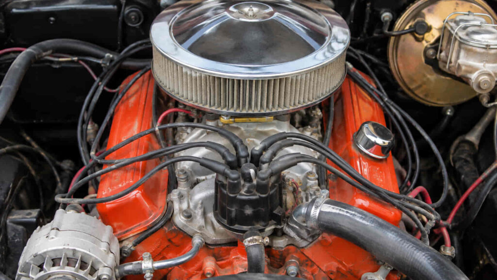
The standard Chevy 350 firing order is 1-8-4-3-6-5-7-2. This sequence determines the order in which the eight cylinders of the Chevrolet 350 Small-Block V8 produce their power strokes. The cylinders are numbered 1, 3, 5, and 7 on the driver side and 2, 4, 6, and 8 on the passenger side, starting at the front of the engine and moving toward the firewall.
The traditional Chevy 350 uses a distributor-based ignition system that delivers electrical voltage to each spark plug in the correct firing sequence. When viewed from above, the distributor rotor rotates clockwise, meaning the spark plug wires must follow the 1-8-4-3-6-5-7-2 sequence clockwise around the distributor cap. Incorrect wire connections can cause engine misfires, rough idling, hard starting, and backfiring.
Understanding the difference between firing order, cylinder numbering, and distributor terminal positions is essential when servicing a Chevrolet 350 engine. This guide explains the Chevy 350 firing order diagram, cylinder locations, distributor rotation, spark plug wire routing, and ignition troubleshooting procedures for traditional 5.7L small-block Chevrolet V8 engines.
What Is the Firing Order of a Chevy 350 Small-Block V8?
The Chevy 350 Small-Block V8 firing order is 1-8-4-3-6-5-7-2. This sequence identifies the order in which the engine’s eight cylinders produce their combustion power strokes. The firing order is determined by the crankshaft and camshaft configuration, ensuring that each cylinder fires at the correct point in the engine’s operating cycle. Traditional Chevrolet 350 small-block engines use this sequence across their standard production configurations, including carbureted and fuel-injected versions.
The Chevrolet 350 is a four-stroke V8 engine, meaning each cylinder completes intake, compression, power, and exhaust strokes during two complete crankshaft revolutions. A full engine cycle requires 720 degrees of crankshaft rotation. Because the engine has eight cylinders with evenly spaced firing events, one cylinder produces a power stroke every 90 degrees of crankshaft rotation. The sequence begins with cylinder 1, continues through cylinders 8, 4, 3, 6, 5, 7, and 2, and then repeats. This arrangement coordinates combustion events with the engine’s mechanical design to maintain consistent power delivery.
On distributor-equipped Chevy 350 engines, the distributor directs ignition voltage to the spark plugs according to the firing order. The distributor rotor rotates clockwise when viewed from above, so the spark plug wires must be connected around the distributor cap in the same clockwise sequence. However, the physical terminal assigned to cylinder 1 depends on the distributor’s installed orientation and correct ignition timing reference. The firing order itself remains unchanged regardless of where the distributor is indexed.
The firing order is a mechanical specification, not an ignition timing adjustment. Changing the spark plug wire sequence does not change the engine’s intended combustion order. Instead, incorrect wire connections can deliver sparks to cylinders at the wrong time, causing misfires, backfiring, hard starting, or an engine that fails to run. Correct wiring must follow the established 1-8-4-3-6-5-7-2 sequence while maintaining the appropriate distributor position and ignition timing.
How Are the Cylinders Numbered on a Chevy 350 Engine?
The Chevy 350 V8 has cylinders 1, 3, 5, and 7 on the driver-side bank and cylinders 2, 4, 6, and 8 on the passenger-side bank. Both banks are numbered from the front of the engine toward the rear, with the front closest to the radiator and the rear closest to the firewall in conventional longitudinal Chevrolet installations. This cylinder numbering arrangement is separate from the firing order and identifies the physical position of each cylinder.
On the driver side, cylinder 1 is located nearest the front of the engine, followed by cylinders 3, 5, and 7 toward the firewall. On the passenger side, cylinder 2 is the frontmost cylinder, followed by cylinders 4, 6, and 8. When standing in front of the vehicle and facing the engine, the driver-side cylinders appear on your right, while the passenger-side cylinders appear on your left. Recognizing this viewing perspective helps prevent confusion when identifying spark plugs and connecting ignition wires.
The Chevy 350 uses an alternating odd-and-even cylinder numbering system rather than numbering each bank consecutively. This differs from some other V8 engines, including the Ford 5.4L Triton, which numbers cylinders 1 through 4 on one bank and 5 through 8 on the opposite bank. For example, cylinder 5 on a Chevy 350 is the third cylinder from the front on the driver side, while cylinder 6 is the third cylinder from the front on the passenger side. The firing sequence does not determine these physical positions.
Correct cylinder identification is essential when replacing spark plugs, installing ignition wires, or diagnosing an engine misfire. For example, if cylinder 7 requires inspection, the technician must locate the rearmost cylinder on the driver-side bank rather than following the firing sequence to its seventh position. Matching the cylinder number to its physical location ensures that the correct spark plug wire, distributor connection, and engine components are inspected during maintenance or troubleshooting.
Read more: 5.4 triton firing order
What Does the Chevy 350 Firing Order Diagram Look Like?
The Chevy 350 firing order diagram shows the combustion sequence 1-8-4-3-6-5-7-2 alongside the physical arrangement of the engine’s eight cylinders. On a traditional Chevrolet 350 Small-Block V8, cylinders 1, 3, 5, and 7 are located on the driver side, while cylinders 2, 4, 6, and 8 are located on the passenger side. Both banks are numbered from the front of the engine toward the firewall. The diagram provides a reference for identifying cylinders before connecting spark plug wires or inspecting ignition components.
When viewing the engine from the front of the vehicle, the driver-side bank appears on your right and the passenger-side bank appears on your left. Cylinder 1 is the frontmost cylinder on the driver side, while cylinder 2 is the frontmost cylinder on the passenger side. Cylinders 7 and 8 are positioned nearest the firewall on their respective banks. These positions remain fixed regardless of the distributor’s installed orientation or the order in which the cylinders fire.
The cylinder layout and distributor wiring diagram serve different purposes. The cylinder layout identifies where each spark plug is installed, while the distributor diagram shows how ignition voltage is distributed through the spark plug wires. For example, cylinder 8 is the rearmost cylinder on the passenger side, but it is the second cylinder in the Chevy 350 firing sequence. Its spark plug wire must connect to the distributor terminal immediately clockwise from the terminal assigned to cylinder 1, assuming the distributor is correctly installed and indexed.
A complete Chevy 350 firing order diagram should therefore identify the cylinder banks, the front of the engine, the firing sequence, and the distributor’s clockwise rotation. Reading these elements together helps prevent crossed spark plug wires and incorrect cylinder identification during ignition system maintenance.
Which Direction Does the Distributor Rotate on a Chevy 350?
The distributor rotor on a traditional Chevy 350 Small-Block V8 rotates clockwise when viewed from above. This rotation determines how the spark plug wires must be arranged around the distributor cap. Starting at the terminal assigned to cylinder 1, the remaining wires connect clockwise in the firing order 1-8-4-3-6-5-7-2. The distributor directs high-voltage ignition pulses to the appropriate spark plugs as the engine rotates, allowing each cylinder to receive a spark near the correct point in its compression stroke.
The distributor is driven mechanically by the engine’s camshaft, which rotates at half the crankshaft speed in a four-stroke engine. During one complete 720-degree crankshaft cycle, the distributor rotor completes one full revolution and passes all eight cap terminals. Because the firing events are evenly spaced, the rotor advances 45 degrees between consecutive ignition events. This relationship allows the distributor to deliver ignition voltage to each cylinder in the specified sequence.
The position of the number 1 terminal is not determined solely by its location on the distributor cap. Its position depends on how the distributor was installed and indexed relative to the engine. On an engine with a correctly installed distributor, the number 1 terminal corresponds to the rotor’s position when cylinder 1 is at the appropriate ignition reference near the end of its compression stroke. If the distributor has been removed or repositioned, the correct terminal must be identified using the engine’s crankshaft position and the distributor’s orientation rather than assuming a universal cap position.
Clockwise distributor rotation must not be confused with ignition timing. Distributor rotation determines the order in which the rotor approaches the cap terminals, while ignition timing determines when the spark occurs relative to piston position. Incorrect wire routing can cause misfires or backfiring even when base ignition timing is properly adjusted. Conversely, correctly routed wires cannot compensate for an incorrectly installed distributor or improper ignition timing. Both the firing sequence and the timing reference must be correct for reliable engine operation.
How Do You Connect Spark Plug Wires on a Chevy 350 Distributor?
To connect spark plug wires on a traditional Chevy 350 distributor, identify the number 1 terminal on the distributor cap and connect the remaining wires clockwise in the firing order 1-8-4-3-6-5-7-2. Each terminal must connect to the spark plug installed in its corresponding cylinder. The correct sequence allows the distributor to deliver ignition voltage to each cylinder at the appropriate point in the engine’s combustion cycle.
Before installing the wires, switch off the ignition and allow the engine to cool. Confirm that the engine is a conventional Chevrolet 350 Small-Block V8 with a distributor-based ignition system. Cylinder 1 is located at the front of the driver-side bank, followed by cylinders 3, 5, and 7 toward the firewall. The passenger-side bank contains cylinders 2, 4, 6, and 8 from front to rear. These physical positions determine where each wire connects at the engine, while the firing order determines its position around the distributor cap.
The number 1 distributor terminal must be identified correctly before routing the remaining wires. On an engine with an existing, properly functioning ignition system, the original number 1 wire position provides a useful reference. If the distributor has been removed, replaced, or repositioned, its orientation must be checked against cylinder 1 at top dead center on the compression stroke. The rotor should point toward the intended number 1 terminal at the appropriate ignition reference. Because distributor indexing can vary, assuming that the number 1 terminal always occupies a particular clock position can lead to incorrect wiring.
Once the number 1 terminal has been established, the wire for cylinder 8 connects to the next terminal clockwise, followed by cylinders 4, 3, 6, 5, 7, and 2. The final terminal completes the sequence before the rotor returns to cylinder 1. Each wire should be fully seated at the distributor cap and spark plug, with its insulation protected from exhaust manifolds, sharp edges, and moving engine components. Proper routing also helps reduce the risk of electrical interference between adjacent ignition wires.
Correct spark plug wire routing requires both the proper firing sequence and accurate distributor indexing. If two wires are crossed, the affected cylinders may receive sparks at the wrong points in their operating cycles, producing rough running, backfiring, or a failure to start. Before attempting to start the engine after installation, verify each connection against the cylinder numbering diagram and confirm that the wires follow the clockwise distributor sequence.
How Do You Find Cylinder 1 and Top Dead Center on a Chevy 350?
Cylinder 1 on a Chevy 350 Small-Block V8 is the frontmost cylinder on the driver-side bank, and its top dead center position occurs when the piston reaches the highest point in the cylinder. However, a four-stroke engine reaches top dead center twice during each complete operating cycle: once at the end of the compression stroke and once at the end of the exhaust stroke. Correct distributor installation requires identifying top dead center on the compression stroke rather than relying on piston position alone.
To locate cylinder 1 at compression top dead center, the engine must be switched off and secured against accidental starting. After removing the number 1 spark plug, the crankshaft can be rotated manually in its normal direction while checking for compression pressure at the spark plug opening. Compression pressure indicates that the piston is approaching the end of its compression stroke, when both intake and exhaust valves are closed. The crankshaft timing mark can then be aligned with the appropriate top dead center reference on the timing indicator. Because timing marks and procedures vary by engine configuration, the correct service information should be used.
The distributor rotor position provides an additional reference when the distributor is installed. With cylinder 1 at compression top dead center, the rotor should be positioned near the distributor cap terminal intended for cylinder 1. The exact alignment depends on distributor installation and the engine’s specified ignition timing. If the rotor points toward a different terminal, the distributor may have been indexed differently or installed incorrectly. The correct number 1 terminal must be established before connecting the remaining spark plug wires clockwise in the 1-8-4-3-6-5-7-2 firing sequence.
Top dead center and ignition timing are related but are not the same measurement. Top dead center describes the piston’s mechanical position, while ignition timing specifies when the spark occurs relative to crankshaft position. Depending on the engine and ignition system, the spark is generally commanded before the piston reaches top dead center on the compression stroke. After distributor installation, base ignition timing must be checked using the procedure and specifications for the particular engine and vehicle. Some electronically controlled distributor systems require a specific timing-check mode or connector procedure before an accurate adjustment can be made.
How Does Duramax Firing Order Relate to Fuel Injection Timing?
Duramax firing order determines the sequence of cylinder power strokes, while fuel injection timing determines when diesel fuel enters each cylinder during the engine cycle. These functions are closely related because combustion must occur at the correct piston position to produce useful power. However, firing order is established by the engine’s mechanical design, whereas injection timing is managed electronically according to operating conditions.
Duramax engines use electronically controlled common rail fuel injection systems that supply pressurized diesel fuel to individual injectors. The engine control module uses crankshaft and camshaft position information to identify engine position and synchronize fuel delivery with the appropriate cylinder. It also considers operating parameters such as engine speed, load, fuel rail pressure, and temperature when calculating injection commands.
A cylinder does not necessarily receive all its fuel in a single injection event. Depending on the engine generation and operating conditions, the control system can divide fuel delivery into pilot, main, and post-injection events. Pilot injection can influence combustion noise and pressure development, while the main injection supplies much of the fuel used to produce engine torque. Post-injection may support emissions-related functions, including exhaust aftertreatment strategies. These events occur within the engine’s operating cycle without changing its established firing order.
Injection timing is measured relative to crankshaft position, commonly using degrees before or after top dead center. Near the end of the compression stroke, the piston approaches top dead center as the air inside the cylinder reaches a high temperature. Fuel injection is coordinated with this process so that combustion develops at an appropriate point in the cycle. Injection timing that is incorrect for the operating conditions can affect combustion efficiency, engine noise, emissions, and performance.
For example, an engine control module may adjust injection timing as engine speed or load changes. The timing of fuel delivery can therefore vary while the cylinder firing sequence remains unchanged. This distinction matters during diagnosis because an injection timing problem and an incorrect cylinder identification are different technical issues. A firing order diagram establishes which cylinder produces the next power stroke, but detailed injection timing specifications must come from service information for the specific Duramax engine.
How Can Duramax Firing Order Help Diagnose Cylinder Misfires?
Duramax firing order helps diagnose cylinder misfires by establishing the combustion sequence and supporting accurate identification of cylinders with abnormal power contribution. When a cylinder produces less torque than expected, the engine may exhibit rough idle, vibration, hesitation, or reduced performance. Diagnostic information can help narrow the investigation to a particular cylinder, but the firing order alone cannot determine the underlying fault.
Modern engine control systems monitor operating conditions and may detect irregularities associated with cylinder performance. Depending on the Duramax generation and diagnostic strategy, a scan tool may display misfire information, cylinder contribution data, injector correction values, or relevant diagnostic trouble codes. These measurements provide different types of evidence and should not be interpreted as interchangeable indicators of injector failure.
The firing sequence helps establish when each cylinder is expected to contribute torque during engine operation. If diagnostic information identifies a cylinder-specific problem, the technician can use the correct cylinder numbering diagram to locate that cylinder and examine its associated systems. For example, a contribution problem attributed to cylinder 7 on a 6.6L Duramax directs attention to the rear cylinder on the passenger-side bank. The firing order identifies its place in the combustion sequence, while the cylinder layout identifies the component location.
A diesel cylinder misfire does not automatically indicate a defective fuel injector. Insufficient fuel delivery, incorrect injection behavior, reduced cylinder compression, valve problems, and certain electrical or control-system faults can all interfere with normal combustion. A cylinder may also produce less power because of a mechanical problem even when its injector receives a valid electrical command.
An effective diagnosis therefore combines cylinder identification with engine-specific testing. Depending on the symptoms and applicable service procedures, technicians may examine fuel system data, perform approved cylinder contribution tests, inspect injector electrical circuits, or evaluate mechanical compression. Results should be compared with manufacturer specifications before replacing components.
Firing order is most useful as a reference that connects combustion events to the correct cylinder. It improves diagnostic accuracy by preventing confusion between firing sequence and physical cylinder location, but a confirmed repair decision requires additional evidence from the affected engine.
Is the Chevy 350 Firing Order the Same for Every 5.7L Chevrolet Engine?
The traditional Chevrolet 350 Small-Block V8 uses the firing order 1-8-4-3-6-5-7-2, but not every Chevrolet engine with a 5.7-liter displacement follows this sequence. The correct firing order depends on the engine family, crankshaft design, and camshaft configuration rather than displacement alone. This distinction is important because Chevrolet produced several generations of 5.7L V8 engines with different ignition systems and mechanical designs.
Conventional Chevy 350 small-block engines, including common carbureted and fuel-injected versions, retain the standard 1-8-4-3-6-5-7-2 firing sequence. Earlier engines commonly use mechanically or electronically controlled distributors, while later applications such as the 5.7L Vortec 350 use updated fuel injection and distributor configurations. Despite these differences, the conventional small-block firing order remains unchanged. However, distributor cap designs, ignition timing procedures, and spark plug wire routing requirements can vary between vehicle models and production years.
The Chevrolet LS1 is a different 5.7L V8 engine that uses the firing order 1-8-7-2-6-5-4-3. Introduced in the 1997 Chevrolet Corvette, the LS1 belongs to General Motors’ Gen III small-block engine family and uses a distributorless ignition system with individual ignition coils. Although the LS1 and traditional Chevy 350 share a nominal displacement of 5.7 liters, their firing sequences and ignition component arrangements are different. Applying a conventional Chevy 350 distributor wiring diagram to an LS1 would therefore be incorrect.
Engine identification should come before selecting a firing order diagram or ignition repair procedure. A traditional distributor-equipped Chevy 350 can be identified by its small-block architecture and distributor location at the rear of the engine. An LS1 uses a different engine architecture and does not have a conventional distributor cap. Checking the engine identification information, model year, and ignition system configuration ensures that the firing order and service instructions match the actual engine.
What Happens If the Chevy 350 Spark Plug Wires Are Connected in the Wrong Order?
Incorrectly connected spark plug wires on a Chevy 350 can cause engine misfires, rough idling, backfiring, hard starting, poor acceleration, or a complete failure to start. These problems occur because the distributor delivers ignition voltage to cylinders at the wrong points in their operating cycles. The Chevy 350 is designed to fire its cylinders in the sequence 1-8-4-3-6-5-7-2, so each distributor terminal must connect to the correct cylinder for combustion to occur at the intended time.
When two spark plug wires are accidentally crossed, the affected cylinders receive ignition pulses intended for different cylinders. A spark may occur when the air-fuel mixture is not properly compressed, preventing efficient combustion and reducing engine power. Depending on the wiring error and engine operating conditions, unburned fuel may enter the exhaust system or combustion may occur at an inappropriate point in the cycle. These conditions can contribute to exhaust backfires, intake backfires, unstable engine speed, and excessive vibration.
The severity of the symptoms depends on how many wires are connected incorrectly and which cylinders are affected. A single wiring mistake involving two cylinders may allow the engine to start while producing a noticeable misfire and reduced performance. More extensive wiring errors can prevent the engine from starting because several cylinders no longer receive sparks at the correct time. For example, connecting the wire for cylinder 8 to the distributor terminal intended for cylinder 4 disrupts the ignition sequence for the affected cylinders, even if the distributor itself is functioning correctly.
Incorrect spark plug wire routing should also be distinguished from improper ignition timing. Crossed wires direct ignition voltage to the wrong cylinders, while incorrect timing causes the spark to occur too early or too late relative to piston position. Both problems can produce rough running or backfiring, but they require different corrective actions. If symptoms begin immediately after replacing spark plug wires or servicing the distributor, verifying the wire connections against the correct firing order is an appropriate first diagnostic step.
The safest correction is to verify each spark plug wire connection with the ignition switched off and the engine cool. Begin by confirming the number 1 distributor terminal, then trace the remaining connections clockwise around the cap in the sequence 1-8-4-3-6-5-7-2. Each wire must lead to the corresponding cylinder according to the Chevy 350 cylinder numbering diagram. If the connections are correct but the symptoms remain, further inspection of ignition timing, spark plugs, distributor components, fuel delivery, and engine mechanical condition may be necessary.
How Can You Check the Chevy 350 Firing Order When Troubleshooting Ignition Problems?
To check the Chevy 350 firing order, verify that the spark plug wires follow the sequence 1-8-4-3-6-5-7-2 clockwise around the distributor cap, starting from the terminal assigned to cylinder 1. Each wire must connect to its corresponding cylinder according to the engine’s numbering arrangement. On a traditional Chevrolet 350 Small-Block V8, cylinders 1, 3, 5, and 7 are located on the driver side, while cylinders 2, 4, 6, and 8 are positioned on the passenger side. Confirming these connections is an essential diagnostic step when an engine develops misfires, backfiring, or starting problems after ignition system maintenance.
The inspection should begin with the ignition switched off and the engine cool. Locate the distributor cap and identify the wire connected to cylinder 1, which is the frontmost cylinder on the driver-side bank. If the engine previously operated correctly and the distributor has not been repositioned, the existing number 1 terminal provides a useful starting reference. However, if the distributor was removed or reinstalled, its indexing must be verified using cylinder 1 at top dead center on the compression stroke. The number 1 terminal cannot be identified reliably from a universal clock position because distributor orientation can vary between installations.
After establishing the correct number 1 terminal, trace the remaining spark plug wires clockwise around the distributor cap. The next terminal must connect to cylinder 8, followed by cylinders 4, 3, 6, 5, 7, and 2. Each connection should be checked against the physical cylinder layout rather than the wire’s apparent length or position in the engine compartment. For example, cylinder 8 is located at the rear of the passenger-side bank, even though it fires immediately after cylinder 1. A wire connected to the wrong cylinder can disrupt combustion timing and produce symptoms that resemble a defective ignition component.
If the spark plug wires are connected correctly but the engine continues to misfire, additional testing is necessary. Worn spark plugs, damaged ignition wires, a defective distributor cap, rotor wear, and ignition coil problems can interrupt spark delivery. Incorrect ignition timing may also cause hard starting, poor acceleration, or backfiring despite correct wire routing. Fuel delivery problems, vacuum leaks, and low cylinder compression can produce similar symptoms, so the firing order should be treated as a reference for diagnosis rather than proof of a specific component failure.
Accurate ignition troubleshooting requires confirming the engine configuration, distributor orientation, spark plug wire connections, and ignition timing before replacing components. The standard Chevy 350 firing order provides the correct combustion sequence, while the cylinder numbering diagram identifies where each wire must terminate. Using both references together helps isolate wiring mistakes, prevents unnecessary parts replacement, and supports a more systematic approach to diagnosing Chevrolet 350 ignition problems.