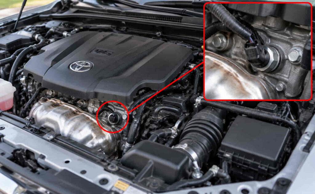
The Toyota knock sensor is mounted directly to the engine where it can detect vibration caused by abnormal combustion, but its exact location depends on the engine family and cylinder layout. On many Toyota 4-cylinder engines, the sensor is attached to the cylinder block on the intake side and may be partially or completely hidden behind the intake manifold. Toyota service information for the 2AZ-FE engine, for example, requires removal of the intake manifold before the knock sensor can be removed.
Toyota V6 and V8 engines can use a different arrangement. Some engines have two knock sensors positioned in less accessible areas of the engine, and reaching them can require removal of the intake manifold, coolant-related components, or other parts that cover the sensor and its wiring. The 1GR-FE V6 used in vehicles such as the Toyota Tacoma uses two knock sensors, illustrating why sensor count and access cannot be determined from the Toyota model name alone.
This guide explains Toyota knock sensor location by engine layout and model, how Bank 1 and Bank 2 relate to sensor identification, whether the intake manifold must be removed, and how codes such as P0325 and P0330 help identify the circuit that needs diagnosis.
What Is the Toyota Knock Sensor Location?
A Toyota knock sensor is typically mounted directly to the cylinder block, but its exact position depends on the engine family rather than the Toyota model name alone. The sensor needs direct mechanical contact with the engine because its purpose is to detect the vibration frequencies associated with abnormal combustion. Toyota’s technical description of its flat-type knock sensor states that the sensor is installed over a stud on the cylinder block and uses a piezoelectric element to detect vibration transmitted through the engine structure.
The physical position changes according to cylinder layout. On many Toyota inline 4-cylinder engines, the knock sensor is mounted on the intake side of the cylinder block and is hidden behind or below the intake manifold. Toyota service procedures for the 2AZ-FE, 2AR-FE, and 2ZR-FE engines all require removal of the intake manifold before the knock sensor is removed. This establishes an important location pattern for common Toyota four-cylinder engines: the sensor may be attached directly to the block but remain invisible during a normal visual inspection from the top of the engine bay.
Toyota V6 engines can use a substantially different arrangement. A V6 has two cylinder banks, which gives Toyota more possible mounting locations and can require multiple knock sensors. The 1GR-FE 4.0-liter V6, for example, uses two knock sensors. Toyota service information instructs the technician to disconnect two knock-sensor connectors and remove two sensors during cylinder-block disassembly. The engine’s service documentation also describes a flat-type knock sensor as being mounted directly to the cylinder block.
This difference explains why a search for “Toyota knock sensor location” cannot be answered reliably with one universal position such as “under the intake manifold” or “on the back of the engine.” Those descriptions may be correct for a particular engine but incorrect for another. A Toyota Camry, for example, has been sold with multiple four-cylinder and V6 engine families across different generations. The model badge therefore identifies the vehicle, while the engine code identifies the mechanical layout that determines the actual sensor location.
The same principle applies when a Toyota engine uses more than one knock sensor. Sensor location must be matched to Toyota’s circuit designation and engine architecture rather than inferred from which side of the vehicle the sensor appears to occupy. This becomes especially important during diagnosis because a trouble code can identify a particular knock-sensor circuit without proving that the sensor itself has failed. The connector, sensor wiring, mounting point, and associated engine bank may all need to be identified before parts are removed.
For practical identification, the engine code is the most useful reference for determining the exact Toyota knock sensor location. A vehicle model and model year can narrow the possibilities, but the engine code confirms whether the vehicle uses an inline-four, V6, V8, or another configuration and identifies the applicable Toyota service procedure. Once the engine is known, the location can be matched to the cylinder block, intake manifold, engine valley, sensor harness, and any components that must be removed for access.
Where Is the Knock Sensor Located on a Toyota 4-Cylinder Engine?
On many Toyota 4-cylinder engines, the knock sensor is mounted directly to the cylinder block on the intake-manifold side of the engine, which means the intake manifold can conceal the sensor from view. This layout is documented on several widely used Toyota four-cylinder engine families, including the 2AZ-FE 2.4-liter, 2AR-FE 2.5-liter, and 2ZR-FE 1.8-liter engines. Their service procedures place intake-manifold removal immediately before knock-sensor removal, confirming that access is from the intake side rather than from the exposed top of the cylinder head.
The 2AZ-FE provides a clear example. This 2.4-liter four-cylinder engine appeared in Toyota applications including the Camry and Highlander. In the 2009 Camry 2AZ-FE service procedure, Toyota requires removal of the throttle body, fuel-related components, and intake manifold before the knock sensor connector and sensor can be reached. A Highlander 2AZ-FE service procedure similarly removes the intake manifold before disconnecting the sensor connector and removing the sensor from the engine. The sensor is therefore not normally visible simply by opening the hood and looking at the exterior of the engine.
The 2AR-FE follows a similar arrangement. This 2.5-liter four-cylinder was used in Toyota vehicles such as the RAV4 and Camry. The 2009 RAV4 2AR-FE knock-sensor procedure begins by removing the intake manifold and then disconnecting the sensor connector and removing the sensor bolt. The 2010 Camry procedure follows the same sequence. This repeated architecture across different vehicles demonstrates why the engine family provides a stronger location signal than the model name: a RAV4 and Camry equipped with the same basic engine family can share the same knock-sensor access pattern.
The 2ZR-FE 1.8-liter engine used in vehicles such as the Toyota Corolla also places the knock sensor behind the intake-manifold assembly. Toyota’s 2012 Corolla procedure requires draining the engine coolant, removing associated intake components, removing the intake manifold, disconnecting the knock-sensor connector, and then removing the sensor from its mounting point. The sensor is again attached to the engine itself rather than to the intake manifold; the manifold is simply the component obstructing access.
Older Toyota four-cylinder engines can follow the same general principle while using different sensor designs and fastening methods. On the 1ZZ-FE 1.8-liter engine, service information calls for removing the intake manifold before disconnecting and removing the knock sensor. The removal tool and sensor design differ from later applications, which is another reason not to identify a replacement sensor or removal procedure solely from the vehicle’s cylinder count.
The location on the cylinder block is functional rather than arbitrary. Combustion knock creates pressure oscillations that generate vibration through the cylinder walls and block. Direct attachment gives the sensor a mechanical path through which those vibrations can reach its piezoelectric sensing element. Toyota’s engine documentation describes the vibration as being transmitted to the sensor’s internal sensing structure, allowing the engine control system to monitor frequencies associated with knock and adjust engine control accordingly.
A Toyota 4-cylinder owner should therefore avoid searching only for a small electrical sensor visible around the valve cover. If the knock sensor cannot be seen from above, inspect the service information for the intake side of the cylinder block before assuming the vehicle does not have an accessible sensor. On several major Toyota four-cylinder engine families, the intake manifold is the component hiding the knock sensor, and removing that manifold is part of the manufacturer-level access procedure.
Read more: Toyota RAV4 Oil Type
Where Is the Knock Sensor Located on a Toyota V6 Engine?
On many Toyota V6 engines, the knock sensors are mounted directly to the engine block in the central area between the two cylinder banks, where the intake manifold or intake air surge tank can hide them from view. This location allows the sensors to detect combustion-related vibration from both sides of the V-shaped engine while protecting them inside the engine’s upper structure. The exact mounting point varies by engine family, so a 1GR-FE 4.0-liter V6 should not automatically be treated the same as a 2GR-FE 3.5-liter V6.
The Toyota 2GR-FE provides a clear example of this arrangement. On the 2008 Toyota Sienna with the 3.5-liter 2GR-FE, Toyota’s service procedure requires removal of the intake air surge tank, fuel-related components, and intake manifold before the two knock control sensors can be disconnected and removed. The presence of two sensors beneath the upper intake components means they are not normally visible from the top of the engine bay. A technician looking around the valve covers or exterior sides of the engine would therefore not see the actual sensors until the intake assembly is removed.
This central location is closely related to the architecture of a V6 engine. Unlike an inline-four, which has one cylinder bank, a V6 contains two banks arranged at an angle to each other. Mounting the sensors around the central block area gives the engine control system a useful mechanical path for detecting vibration generated by combustion events on either side of the engine. The sensors remain physically attached to the engine structure; the intake manifold does not detect knock but instead covers the area where the sensors are installed.
The 1GR-FE 4.0-liter V6 used in Toyota trucks and SUVs also uses two knock sensors, but its service layout illustrates why Toyota V6 locations should be identified by engine code rather than cylinder count alone. Toyota service information for a 2010 Tacoma 1GR-FE shows two knock-sensor connectors and two sensors. Access requires extensive disassembly that includes removal of the intake manifold and water-outlet-related components before the sensors are reached. The procedure confirms that the sensors sit deep enough within the engine assembly that they cannot be treated as easily accessible external sensors.
Earlier Tacoma service information for the same 1GR-FE engine shows the same two-sensor architecture. The removal procedure calls for taking off the intake manifold and additional engine components before the two sensor connectors and sensors can be accessed. This repeated configuration across different model years demonstrates an important semantic relationship: the Toyota model identifies the vehicle, but the engine family determines the knock sensor location and access path.
The V6 layout also explains why Bank 1 and Bank 2 terminology becomes important during diagnosis. A V6 engine has two cylinder banks, but the physical left or right side of the vehicle should not be used as a universal shortcut for identifying a bank. Toyota defines Bank 1 according to the bank containing cylinder No. 1. Sensor and circuit designations must therefore be matched to the engine’s firing order and cylinder numbering rather than assumed from the driver or passenger side.
This distinction becomes especially important when a scan tool reports a knock-sensor-related code. A code associated with one circuit does not mean that the first visible connector or the sensor closest to one side of the engine is automatically the correct part to replace. On Toyota V6 engines with two sensors hidden beneath the intake assembly, the engine diagram and diagnostic information should be used to identify which connector and sensor correspond to the affected circuit before disassembly begins.
The number of components that must be removed also affects diagnostic strategy. When the sensor is buried under the intake manifold, replacing it can require substantially more labor than replacing a sensor mounted externally on the cylinder block. Wiring and connectors in the same covered area should therefore be considered during diagnosis because opening the intake assembly only to replace an electrically functional sensor can lead to unnecessary work.
For Toyota V6 vehicles, the most reliable location description is that the knock sensors are mounted to the engine block and, on major engine families such as the 2GR-FE and 1GR-FE, are concealed beneath or behind upper intake components that must be removed for access. The exact position, sensor count, and disassembly path should then be confirmed from the engine code.
Where Is the Knock Sensor Located on a Toyota V8 Engine?
Toyota V8 knock sensors are commonly located in the central V-shaped area of the engine beneath the intake manifold, although the number of sensors and exact mounting arrangement depend on the V8 engine family. Older engines such as the 2UZ-FE 4.7-liter V8 use two knock sensors, while Toyota’s later 3UR-FE 5.7-liter V8 uses four. Both configurations demonstrate why the sensor location cannot be determined accurately from the statement “Toyota V8” alone.
The 2UZ-FE used in vehicles such as the Toyota Land Cruiser, Tundra, and 4Runner places its two knock sensors beneath the intake system. Toyota service information for a 2006 Land Cruiser 2UZ-FE requires removal of the V-bank cover, intake-air components, intake manifold assembly, and air-pump assembly before the two knock sensor connectors and sensors are reached. The two sensors are therefore located in the central engine area rather than being mounted in an easily visible position on the exterior of the cylinder heads.
The same architecture appears in Toyota 4Runner applications. Service information for a 2005 4Runner with the 4.7-liter 2UZ-FE directs the technician to remove the intake manifold assembly and related components before accessing the knock sensors. A 2007 Tundra equipped with the 2UZ-FE similarly requires intake-manifold removal before the two sensors can be disconnected and removed. The repetition across three different Toyota models confirms that the engine family, rather than whether the vehicle is a Land Cruiser, 4Runner, or Tundra, is the stronger predictor of sensor location.
The later 3UR-FE 5.7-liter V8 uses a different sensor arrangement. Toyota service information for a 2009 Tundra identifies four knock sensors, not two. The intake manifold and additional upper-engine components must be removed before the four electrical connectors and four sensors are accessible. This is an important difference because a generic statement that “a Toyota V8 has two knock sensors under the intake” would be correct for some 2UZ-FE applications but incorrect for the 3UR-FE.
The central mounting location serves the same mechanical purpose seen on Toyota V6 engines. Combustion knock creates pressure fluctuations that transmit vibration through the cylinder block. Positioning the sensors directly on the engine structure gives their piezoelectric elements a solid mechanical path through which those vibrations can be detected. On a V8, the sensors must monitor combustion events across two cylinder banks and eight cylinders, so Toyota can use multiple sensors to provide sufficient detection coverage for the engine-management system.
The intake manifold is therefore an important location reference but should not be confused with the actual sensor mounting point. Saying that a Toyota V8 knock sensor is “under the intake manifold” describes how the sensor is accessed. The sensor itself is mounted to the engine structure below that manifold. This distinction matters when identifying the part because electrical connectors, harness sections, coolant components, or other devices may also occupy the same engine valley.
The hidden location also explains why Toyota V8 knock-sensor repairs can involve more labor than the sensor’s size suggests. The sensor may be a relatively small component, but intake assemblies, wiring, air-injection equipment, coolant passages, or other upper-engine components can block access. On the 2UZ-FE, Toyota’s service sequence places several of these components between the technician and the knock sensors. On the 3UR-FE, the four sensors are likewise reached only after removal of the intake manifold and components above the sensor area.
This location should also influence diagnosis. A stored knock-sensor circuit code should not automatically trigger intake-manifold removal and sensor replacement. Because the sensor wiring and connectors occupy the same concealed area, an open circuit, damaged connector, harness problem, or poor electrical connection can produce a diagnostic result that resembles sensor failure. Confirming the engine code, diagnostic circuit, and sensor designation before disassembly reduces the risk of opening the intake system to replace the wrong component.
For Toyota V8 engines, the central engine valley beneath the intake manifold is the primary location to investigate, but the exact number and mounting pattern must be matched to the engine family. A 2UZ-FE commonly uses two sensors in this area, while a 3UR-FE uses four. Identifying the engine code first provides a more accurate location than relying on the Toyota model name or V8 designation alone.
Where Is the Toyota Knock Sensor Located by Model?
The Toyota knock sensor location varies by model because Toyota vehicles have used different engine families, even when the same model name remained in production for many years. A Camry, Corolla, RAV4, Tacoma, Highlander, Sienna, 4Runner, or Tundra does not have one permanent knock sensor location across every generation. The engine code provides the more reliable reference because it determines the cylinder layout, number of knock sensors, mounting position, and components that must be removed to reach them.
On Toyota Camry models equipped with the 2AZ-FE 2.4-liter four-cylinder engine, the knock sensor is mounted to the cylinder block behind the intake manifold. Toyota’s 2009 Camry service procedure requires removal of the throttle body, fuel delivery components, and intake manifold before the knock sensor connector and sensor can be reached. Earlier 2AZ-FE Camry service information shows the same basic arrangement. This means a 2AZ-FE Camry owner normally cannot identify the sensor by looking around the valve cover or the exposed front of the engine; the intake manifold blocks direct access.
Toyota Corolla models using the 2ZR-FE 1.8-liter four-cylinder follow a similar location pattern. On the 2012 Corolla, Toyota service information requires removal of the intake manifold before disconnecting and removing the knock sensor. The sensor is mounted directly to the engine rather than to the manifold itself, but the manifold occupies the access path. This arrangement makes “behind or beneath the intake manifold on the cylinder block” a useful location description for the 2ZR-FE, while the exact mounting point should still be confirmed from the applicable service diagram.
Toyota RAV4 models equipped with the 2AR-FE 2.5-liter four-cylinder also place the knock sensor behind the intake manifold. Toyota’s service procedure for both 2009 and 2012 RAV4 applications begins knock-sensor removal by taking off the intake manifold, after which the electrical connector and sensor retaining bolt are accessible. This establishes a strong engine-family pattern: when a RAV4 uses the 2AR-FE, the sensor is located on the intake side of the engine block rather than in an exposed position around the cylinder head.
The model name becomes even less reliable when Toyota offers different engines within the same vehicle generation. A RAV4 with a four-cylinder engine can have a single knock-sensor arrangement that differs substantially from a V6-equipped RAV4. A Camry four-cylinder and Camry V6 can likewise require different access routes even though both vehicles carry the same model badge. Toyota knock sensor location should therefore be matched to the engine first and the vehicle model second.
Toyota Highlander and Sienna models equipped with the 2GR-FE 3.5-liter V6 use a two-sensor arrangement concealed beneath the upper intake system. Toyota Sienna service information requires removal of the intake air surge tank, fuel-related components, and intake manifold before the two knock control sensor connectors and sensors are reached. The location is therefore deeper in the central V6 structure than on a typical inline-four engine. Because Highlander applications have also used multiple engines across different years, the 2GR-FE engine designation is more useful than “Highlander knock sensor location” as a standalone description.
Toyota Tacoma and 4Runner models equipped with the 1GR-FE 4.0-liter V6 also use two knock sensors mounted within the engine assembly rather than as simple externally exposed sensors. Access on the 1GR-FE requires removal of upper intake and related components before the sensor area can be reached. A Tacoma owner with the four-cylinder engine should not use this V6 location as a reference, because the alternative engine has a different cylinder layout and knock-detection arrangement. The same logic applies to the 4Runner, which has been offered with more than one engine family across its production history.
Toyota Tundra models demonstrate why sensor count must also be matched to engine family. A Tundra equipped with the older 2UZ-FE 4.7-liter V8 uses two knock sensors beneath the intake system, while the 3UR-FE 5.7-liter V8 uses four knock sensors. Toyota’s 3UR-FE service procedure requires removal of the intake manifold and separator case before four electrical connectors and four sensors are disconnected and removed. A generic search result stating that a “Tundra has two knock sensors under the intake” can therefore be correct for one engine and incorrect for another.
The same engine-based reasoning should be used for Toyota Land Cruiser and Sequoia applications. These vehicles have used several V8 engine families across different years and markets. When the vehicle uses the same engine family as another Toyota model, its knock-sensor architecture can be closely related even though the vehicle itself is different. This is why repair information is commonly organized under engine codes such as 2UZ-FE, 1GR-FE, 2GR-FE, or 3UR-FE rather than relying only on a model name.
For practical diagnosis, identify the Toyota model year and engine code before using a knock sensor location diagram. A location image for a 2AR-FE RAV4 can be useful for another applicable 2AR-FE installation, while an image from a V6 RAV4 may point to a completely different part of the engine. Matching the engine family prevents a correct location for one Toyota configuration from becoming incorrect information for another.
How Many Knock Sensors Does a Toyota Have?
A Toyota can have one, two, or four knock sensors depending on the engine design, so there is no universal sensor count for all Toyota vehicles. Many inline four-cylinder Toyota engines use a single knock sensor, several V6 engines use two, and certain Toyota V8 engines use either two or four. The number of cylinders provides a useful clue, but the engine family and Toyota’s engine-control strategy determine the actual sensor count.
The 2AZ-FE, 2AR-FE, and 2ZR-FE four-cylinder engines use a single knock sensor in the service procedures discussed above. Toyota documentation for each engine refers to one connector and one sensor after the intake manifold is removed. This single-sensor layout allows the engine control module to monitor block vibration across the inline cylinder arrangement from one calibrated mounting position.
Toyota V6 engines commonly require broader sensing coverage because the cylinders are divided between two banks. The 2GR-FE 3.5-liter V6 uses two knock control sensors in the Sienna application documented by Toyota service information. The removal procedure specifically calls for disconnecting two connectors and removing two sensors beneath the intake assembly. The 1GR-FE 4.0-liter V6 likewise uses a two-sensor architecture in applicable Tacoma and 4Runner configurations. Sensor count therefore becomes part of identifying the correct component during diagnosis, especially when a scan tool refers to a particular knock-sensor circuit.
Toyota V8 engines illustrate that cylinder count alone does not predict sensor count. The 2UZ-FE 4.7-liter V8 commonly uses two knock sensors, while the later 3UR-FE 5.7-liter V8 uses four knock sensors. Toyota service documentation for the 3UR-FE explicitly instructs the technician to disconnect four knock-sensor connectors and remove four sensors after gaining access beneath the intake system. The additional sensors give Toyota more sensing points across the larger cylinder block and demonstrate why a technician should not assume that one sensor corresponds directly to one cylinder bank.
The sensor count also affects how diagnostic codes should be interpreted. A vehicle with one sensor has a simpler physical identification problem than an engine with two or four sensors hidden under the intake manifold. When multiple sensors are present, Toyota’s diagnostic designation must be matched to the correct circuit, connector, sensor position, and engine bank. Replacing whichever sensor is easiest to reach is not a valid diagnostic method because several physically similar sensors can occupy the same concealed area.
A multiple-sensor Toyota engine also does not necessarily use the terms Bank 1 and Bank 2 as a direct one-to-one naming system for every knock sensor. The ECM diagnostic strategy can distinguish sensors or circuits according to Toyota’s service definitions, and those definitions should be used instead of assuming that every sensor physically nearest Bank 1 is automatically called “Bank 1 knock sensor.” This becomes particularly important on engines such as the 3UR-FE that use more sensors than cylinder banks.
The most reliable way to determine how many knock sensors a Toyota has is to identify the engine code and consult the corresponding Toyota service information. A four-cylinder Toyota may use one sensor, a V6 may use two, and a V8 may use two or four, but these are engine-family patterns rather than universal rules. Confirming the engine architecture before diagnosis also establishes where the sensors are mounted and how much disassembly is required to reach them.
Where Are Toyota Bank 1 and Bank 2 Knock Sensors Located?
On a Toyota engine with two cylinder banks, Bank 1 is the bank that contains cylinder No. 1, while Bank 2 is the opposite bank. This definition is more reliable than identifying a knock sensor by the driver side or passenger side because Toyota has used different longitudinal and transverse engine layouts across Camry, Highlander, Sienna, Tacoma, Tundra, 4Runner, Sequoia, and other models. Toyota service information for the 2UZ-FE V8 explicitly defines Bank 1 as the bank containing cylinder No. 1 and Bank 2 as the bank that does not contain cylinder No. 1.
The physical knock sensor location still depends on the engine family. On Toyota V6 and V8 engines with two sensors, one sensor or sensing circuit monitors the Bank 1 side and another monitors the Bank 2 side. The sensors themselves are generally mounted directly to the cylinder block because block vibration provides the mechanical signal used to detect abnormal combustion. On engines where the sensors are positioned within the V-shaped central area, the intake manifold can hide both sensors even though each circuit corresponds to a different bank.
A Toyota 1MZ-FE 3.0-liter V6 illustrates this arrangement. Toyota diagnostic information identifies P0325 with the Bank 1 knock sensor circuit and P0330 with the Bank 2 circuit. The engine uses sensors on the two sides of the cylinder block, but identifying those sides correctly still requires Toyota’s cylinder numbering rather than a universal left-versus-right rule.
The same principle applies to the 3MZ-FE V6. Toyota service information groups P0325, P0327, and P0328 with the Bank 1 knock sensor circuit, while P0330, P0332, and P0333 relate to the Bank 2 circuit. This makes the bank designation useful during diagnosis because it narrows the fault to one side of the engine’s knock-detection system, but the technician still needs the engine-specific cylinder diagram to locate that side physically.
Right-bank and left-bank terminology can create confusion because Toyota documentation does not support one universal statement such as “Bank 1 is always the passenger side.” On a 2001 5VZ-FE Tundra, service information associates P0325 with the right-bank circuit and P0330 with the left-bank circuit. On certain 2UZ-FE Tundra documentation, however, P0325 is identified with the left-bank circuit and P0330 with the right-bank circuit. These differences demonstrate why Bank 1 should be identified from cylinder No. 1 rather than from the physical side of the vehicle.
Inline four-cylinder Toyota engines require a different interpretation because they have only one cylinder bank. A 2AZ-FE four-cylinder, for example, uses a knock sensor mounted to the cylinder block and Toyota diagnostic information can describe P0325 as Knock Sensor 1 Circuit Bank 1 even though there is no second physical cylinder bank. In this context, “Bank 1” reflects standardized OBD terminology rather than indicating that the vehicle has another Bank 2 knock sensor waiting on the opposite side.
Sensor numbering should also not be confused automatically with cylinder-bank numbering. A Toyota engine can have one, two, or more knock sensors depending on its design. The 3UR-FE V8, for example, uses four knock sensors despite having only two cylinder banks. On such an engine, a generic assumption that “Sensor 1 equals Bank 1 and Sensor 2 equals Bank 2” cannot describe the complete physical system. Toyota’s engine-specific wiring diagram and sensor designations are required to identify each component accurately.
For diagnosis, first determine which bank contains cylinder No. 1, then match the diagnostic circuit to Toyota’s sensor-location diagram for that engine. This approach prevents a common repair error in which a sensor is selected because it appears to be on the driver or passenger side rather than because it belongs to the circuit identified by the ECM.
Do Toyota Codes P0325 and P0330 Tell You Which Knock Sensor Is Faulty?
Toyota codes P0325 and P0330 identify a knock sensor circuit that requires diagnosis, but they do not prove that the knock sensor itself has failed. On applicable Toyota engines, P0325 generally identifies the Knock Sensor 1 or Bank 1 circuit, while P0330 identifies the Knock Sensor 2 or Bank 2 circuit. Toyota service information nevertheless requires the complete circuit to be checked because the sensor, connector, wiring harness, and ECM-side circuit can all affect the signal received by the engine control module.
P0325 is especially important for locating the correct circuit on engines with multiple knock sensors. Toyota service documentation for a 1MZ-FE V6 identifies P0325 as a Knock Sensor 1 Circuit Malfunction for Bank 1. The knock sensors are mounted to the right and left sides of the cylinder block, and the ECM monitors their electrical signals while the engine operates. When the expected knock-sensor signal falls outside Toyota’s diagnostic criteria, the ECM can store the DTC and use a fail-safe ignition strategy.
On an inline four-cylinder Toyota with one knock sensor, P0325 normally points to that single knock-sensor circuit rather than forcing the technician to find a second physical bank. Toyota’s 2AZ-FE diagnostic information describes the sensor as being fitted to the cylinder block and identifies P0325 as the relevant circuit fault. This is why the same OBD code can lead to a physically different location depending on whether the Toyota engine is an inline-four, V6, or V8.
P0330 becomes relevant on engines that have a second monitored knock-sensor circuit. Toyota service information for the 2UZ-FE V8 identifies P0330 as Knock Sensor 2 Circuit, Bank 2, while the corresponding documentation defines Bank 2 as the bank that does not contain cylinder No. 1. The code therefore helps narrow the diagnostic area, but the engine-specific cylinder layout is still required to translate “Bank 2” into an exact physical position.
The code should not be interpreted as a direct replacement command because the ECM monitors an electrical signal, not the mechanical condition of the sensor in isolation. An open circuit, damaged harness, loose or contaminated connector, connection problem beneath the intake manifold, or sensor fault can interrupt the expected signal. Toyota diagnostic procedures consequently include circuit inspection rather than instructing the technician to replace the sensor immediately after retrieving P0325 or P0330. The importance of the wiring increases on engines where the sensor and harness are buried beneath the intake assembly because both components can require similar disassembly to access.
Toyota also recommends using freeze-frame information during diagnosis on applicable systems. The recorded data shows operating conditions when the ECM detected the malfunction, such as whether the engine was running, whether it had warmed up, and other engine conditions. That information does not provide the physical knock sensor location, but it helps distinguish a confirmed circuit problem from assumptions based only on the presence of the check-engine light.
The relationship can therefore be stated precisely: P0325 normally directs diagnosis toward Knock Sensor 1 or the Bank 1/single-sensor circuit, while P0330 directs diagnosis toward Knock Sensor 2 or the Bank 2 circuit on applicable Toyota engines. The code identifies where diagnosis should begin within the knock-sensor system; it does not establish that the sensor is the only possible failed component.
Before replacing a Toyota knock sensor after either code appears, the correct sequence is to identify the engine family, determine the applicable Bank 1 or Bank 2 position from Toyota’s cylinder numbering, locate the corresponding sensor and connector, and inspect the associated circuit. This keeps the diagnostic decision tied to the exact Toyota engine rather than to a generic OBD description.
Is the Toyota Knock Sensor Under the Intake Manifold?
The Toyota knock sensor is located under the intake manifold on many Toyota engines, but this is not a universal location for every Toyota model or engine family. The sensor itself is mounted directly to the engine structure, usually the cylinder block, while the intake manifold sits above or in front of the sensor and blocks access. This distinction matters because “under the intake manifold” describes the sensor’s access location rather than the component to which the sensor is attached.
Toyota V6 and V8 engines provide the clearest examples of this layout. On the 2UZ-FE 4.7-liter V8 used in vehicles such as the Sequoia, Land Cruiser, Tundra, and 4Runner, Toyota service procedures require removal of the intake manifold assembly before the two knock sensors can be inspected or removed. On some versions, both the upper and lower intake manifold assemblies must be removed before the sensors become accessible. The sensors are therefore positioned within the central V-shaped area of the engine and remain hidden during a normal inspection from above.
The 3UR-FE 5.7-liter V8 follows the same broad location pattern but uses a different sensor configuration. Toyota service information for the Tundra, Sequoia, and Land Cruiser requires intake manifold removal before the knock sensors can be reached. On documented 3UR-FE applications, four knock sensor connectors and four sensors are located beneath the upper engine components. Certain procedures also require removal of a separator case or engine covers after the manifold has been removed, showing that the sensors are positioned deeper in the engine assembly than the phrase “under the intake” alone may suggest.
The 2UZ-FE also demonstrates why model-specific service information remains necessary even when the general location is known. On a 2007 Tundra 4.7-liter V8, Toyota directs the technician to remove the intake manifold, water bypass pipe, and an air-injection hose before disconnecting the two knock sensor connectors and removing the sensors. The knock sensors are still under the intake area, but additional components occupy the access path. Knowing that the sensor is beneath the manifold therefore identifies the correct region of the engine without necessarily describing every obstruction between the technician and the sensor.
The same relationship occurs on many Toyota four-cylinder engines, although their cylinder layout does not create an engine valley. Engines such as the 2AZ-FE, 2AR-FE, and 2ZR-FE commonly mount the knock sensor on the intake side of the cylinder block, with the intake manifold covering the sensor or restricting direct access. In these engines, the sensor can still accurately be described as being behind or beneath the intake manifold even though it is not located in a V-shaped valley between two cylinder banks.
This mounting strategy serves a mechanical purpose. The knock sensor must detect vibration transmitted through the engine block, so Toyota installs it against a solid structural part of the engine instead of placing it on the intake manifold itself. Combustion knock generates pressure oscillations inside the cylinders, and those oscillations create vibrations through the block. Direct mechanical contact allows the sensing element to detect those vibrations so the engine control system can respond through ignition-control adjustments.
The intake manifold can make the sensor appear more difficult to locate than other engine-management sensors. Components such as the mass airflow sensor, camshaft position sensors, or some temperature sensors may be visible around the exterior of the engine, while a knock sensor can remain completely concealed. A vehicle owner may therefore see the wiring leading toward the engine without being able to see the sensor at the end of that circuit.
Location diagrams should also be interpreted according to engine orientation. A diagram showing a knock sensor in the center of a V8 engine can look very different from a photograph taken with the intake manifold installed. Likewise, the intake-side mounting position of an inline-four can be hidden by runners, wiring, hoses, and fuel-system components. Matching the diagram to the engine code prevents surrounding components from being mistaken for the sensor.
“Under the intake manifold” is therefore an accurate description for many Toyota knock sensor applications, especially several four-cylinder, V6, and V8 engines, but the exact mounting point must still be confirmed by engine family. The knock sensor remains attached to the engine block or related engine structure; the intake manifold is primarily the component that prevents direct visual and physical access.
Do You Have to Remove the Intake Manifold to Reach a Toyota Knock Sensor?
The intake manifold must be removed to reach the knock sensor on many Toyota engines, particularly when the sensor is mounted in the engine valley or on the intake side of the cylinder block, but intake-manifold removal is not a universal requirement for every Toyota engine. The correct access procedure is determined by the engine family, which is why Toyota service information should be checked before beginning disassembly.
Toyota’s 2UZ-FE V8 is a direct example. On a 2005 Sequoia 4.7-liter V8, Toyota instructs the technician to remove the intake manifold assembly before inspecting the two knock sensors. The procedure reverses the sequence after sensor service by reinstalling the intake manifold before the remaining intake components. The manifold is therefore not removed merely to create additional working room; it physically covers the sensor-access area.
Some 2UZ-FE applications require even more intake disassembly. Toyota’s 2005 Land Cruiser procedure calls for removal of both the upper and lower intake manifold assemblies before the two knock sensors are inspected. Earlier Tundra service information follows the same pattern, requiring upper and lower manifold removal before the knock sensor connectors can be accessed. These procedures confirm that the sensor is deep enough within the V8 engine structure that attempting to reach it without removing the specified intake components does not follow the manufacturer repair path.
Later 2UZ-FE applications can include additional components between the intake manifold and the sensor. Toyota’s service procedure for a 2006 Land Cruiser requires intake manifold removal and removal of the air pump assembly before the two knock control sensors can be disconnected. A 2007 Tundra procedure similarly includes the water bypass pipe and an air-injection hose after the manifold is removed. This means the labor involved in reaching a knock sensor can be considerably greater than the sensor’s small physical size suggests.
The 3UR-FE 5.7-liter V8 also requires intake manifold removal. Toyota’s procedures for the Tundra and Sequoia list intake manifold removal before access to the four knock sensors. Certain 3UR-FE procedures then require removal of cylinder-head covers, engine covers, or the separator case before the four connectors and sensors are exposed. The sequence confirms that these sensors cannot simply be unplugged from the exterior of the engine while the intake remains assembled.
Intake-manifold removal is also required on several common Toyota four-cylinder engines discussed earlier in this article. The 2AZ-FE, 2AR-FE, and 2ZR-FE locate the sensor on the intake side of the cylinder block, so the manifold occupies the normal access path. The mechanical layout differs from a V8 engine valley, but the repair consequence is similar: the sensor is attached to the block and the intake assembly must be moved before the sensor can be reached.
This access requirement has an important diagnostic consequence. A difficult-to-reach knock sensor should be diagnosed before major intake disassembly begins. A stored P0325 or P0330 does not prove that the sensor itself has failed. The diagnostic circuit also contains wiring, connectors, and ECM connections, and an electrical fault can produce the same broad circuit code. When reaching the sensor requires manifold removal, replacing it without verifying the relevant circuit can result in substantial unnecessary labor.
The concealed harness should receive particular attention because Toyota knock sensor wiring can share the same difficult access area as the sensor. Once the intake manifold has been removed, the connector and protected harness sections become accessible together with the sensing element. Damage to wiring, poor terminal contact, contamination, or an open circuit should not be ignored simply because the sensor is physically nearby.
Removing the intake manifold can also disturb other systems unrelated to the knock sensor. Depending on the engine, service procedures can involve fuel lines, throttle-body connections, coolant passages, vacuum hoses, air-injection components, gaskets, and electrical connectors. Toyota’s documented 2UZ-FE and 3UR-FE procedures illustrate this relationship by requiring several surrounding components to be moved before the sensors are exposed.
For this reason, the knock sensor’s location should be confirmed before interpreting “sensor replacement” as a simple external repair. If Toyota service information places the sensor beneath the intake manifold, the manifold or associated upper-engine assembly normally has to be removed through the specified access path. If the sensor is externally accessible on another engine family, unnecessary intake removal should be avoided. The engine code and manufacturer repair procedure determine which situation applies.
How Can You Identify a Toyota Knock Sensor Before Removing It?
A Toyota knock sensor can be identified by its direct mounting position on the cylinder block, its electrical connector, and its location within the engine’s documented knock-sensor circuit. Unlike sensors installed in an intake duct, coolant passage, or exhaust system, the knock sensor needs firm mechanical contact with the engine structure so vibration from combustion can reach its sensing element. Toyota service information repeatedly describes the knock sensor as being fitted directly to the cylinder block, which makes mounting location the strongest physical clue when distinguishing it from nearby engine sensors.
The sensor’s operating principle also explains its physical design. Toyota knock sensors contain a piezoelectric element that generates an electrical voltage when engine-block vibration deforms the sensing element. Toyota documentation for the 2AZ-FE describes a flat-type, non-resonant knock sensor capable of detecting vibration across approximately 6 to 15 kHz, while 3UR-FE documentation describes a similar sensor operating across approximately 5 to 15 kHz. The exact frequency range varies by engine and sensor design, but the relationship remains the same: the sensor must be mechanically coupled to the block because engine vibration is the signal being measured.
This mechanical relationship helps distinguish a knock sensor from other electrical components under the intake manifold. A coolant temperature sensor is associated with a coolant passage, an oil-pressure-related sensor or switch is associated with the lubrication system, and camshaft or crankshaft position sensors are located where they can detect rotating engine components. A knock sensor instead attaches to the block specifically to monitor vibration. When several connectors and harness branches are visible after the intake manifold has been removed, following Toyota’s engine-specific wiring diagram is more reliable than identifying the component by connector shape alone.
Sensor appearance should not be treated as universal. Toyota has used different knock sensor designs across engine generations. Some are compact flat-style sensors secured against the cylinder block, while earlier engines may use a different housing or fastening method. Two sensors from different Toyota engines can therefore look different even though they perform the same basic function. Engine code, connector routing, mounting position, and Toyota service information provide a more reliable identification method than searching for a component that visually resembles a photograph from another vehicle.
The number of sensors can also help confirm identification. A 2AZ-FE four-cylinder application can use one knock sensor on the block, while a 2UZ-FE V8 uses a sensor on each cylinder-bank side and a 3UR-FE uses multiple knock sensors across the engine. Toyota’s 2UZ-FE diagnostic information specifically describes sensors mounted on the right and left sides of the cylinder block, while 3UR-FE documentation describes multiple block-mounted knock sensors monitored by the ECM. A technician working on a multi-sensor engine should therefore expect more than one similar connector in the same general engine area.
The wiring path is another identification clue. The knock sensor connector leads into the engine control harness and ultimately communicates with the ECM through the knock-sensor circuit. On engines where the sensor is concealed beneath the intake manifold, part of this harness can also be hidden. Following the documented wiring route helps separate a knock sensor connector from nearby fuel-injector, coolant, or intake-related connections. This is particularly important before disassembly because unplugging the wrong connector can create additional diagnostic codes that were not present before the repair.
Toyota diagnostic trouble codes can narrow the identification further, but they should be used together with the engine diagram. On a single-sensor engine, P0325 or a related knock-sensor code directs attention to the single block-mounted sensor circuit. On engines with two banks, Toyota may distinguish Bank 1 and Bank 2 circuits. Toyota documentation for the 2UZ-FE defines Bank 1 as the bank containing cylinder No. 1 and Bank 2 as the opposite bank, which allows the technician to match the fault to the correct sensor area instead of relying on vehicle left/right assumptions.
The most reliable way to identify a Toyota knock sensor before removing it is to match the engine code, cylinder-block location, connector, sensor count, and Toyota wiring diagram to the same component. Physical appearance alone is not sufficient because Toyota has used multiple sensor designs and engine layouts. Confirming these attributes before loosening the sensor reduces the risk of removing another engine-management component or replacing the wrong sensor on a multi-bank engine.
What Does a Bad Toyota Knock Sensor Look Like During Diagnosis?
A bad Toyota knock sensor is identified primarily through diagnostic signal behavior and circuit testing rather than through visible physical damage. A sensor can appear normal externally while producing an incorrect signal, and a stored knock-sensor DTC can also be caused by wiring or connector faults. Toyota diagnostic procedures therefore evaluate the sensor circuit, signal behavior, wiring, and ECM connection rather than instructing technicians to judge the component by appearance alone.
Toyota’s engine-control system expects the knock sensor to produce a characteristic electrical response when the cylinder block vibrates. The piezoelectric element generates voltage in response to mechanical vibration, and the ECM uses that signal to determine whether combustion knock is occurring. When knock is detected, ignition timing can be retarded to reduce the abnormal combustion. The ECM also monitors whether the sensor signal falls within an expected operating range, allowing abnormal circuit behavior to trigger diagnostic trouble codes.
Older Toyota diagnostic procedures illustrate how signal quality can be evaluated directly. Service information for the 3S-FE RAV4 instructs technicians to examine the knock-sensor waveform with an oscilloscope and compare its vibration frequency with the specified value. Toyota documentation for this application identifies a normal-mode sensor frequency of approximately 7.6 kHz and treats a signal outside the specified behavior as evidence of sensor malfunction. Other Toyota engines use different calibrated frequencies, which means the numerical specification must come from the service information for the exact engine rather than from a generic Toyota value.
A stored P0325, P0327, P0328, P0330, P0332, or related code does not automatically mean the sensor housing itself is defective. These codes describe circuit behavior detected by the ECM. Toyota’s service information for multiple engine families includes wiring diagrams and circuit inspection steps because an open circuit, short, connector problem, damaged harness, or ECM-side fault can interfere with the same signal that a failed sensor would affect. A replacement decision made solely from the DTC can therefore result in replacing a functional sensor while leaving the actual wiring problem unresolved.
The engine’s operating behavior can provide supporting evidence but is also not conclusive by itself. When Toyota detects certain knock-sensor circuit faults, the ECM can enter a fail-safe strategy and retard ignition timing. Toyota service information for several engines describes the corrective retard value being set aggressively during fail-safe operation. A driver may experience reduced engine response or performance because the ECM is using a conservative ignition strategy, but those symptoms do not distinguish a failed sensor from an open or damaged sensor circuit.
Freeze-frame information can add diagnostic context. Toyota diagnostic procedures for P0325 instruct technicians to review recorded engine conditions from the moment the malfunction was detected. This can show whether the engine was running, whether it was warmed up, and other operating conditions relevant to the fault. Freeze-frame data does not identify the sensor’s physical location, but it helps establish when the circuit failed and prevents diagnosis from relying only on a check-engine light that may have appeared under a very specific operating condition.
Physical inspection still has value once the sensor area is accessible. A damaged connector, pin problem, deteriorated harness, contamination, or obvious mechanical damage can explain why the ECM is no longer receiving the expected signal. On Toyota engines where the knock sensor is located under the intake manifold, this inspection becomes particularly important because both the sensor and its concealed wiring are exposed during the same disassembly. Replacing the sensor while ignoring a damaged harness in the same area can leave the original DTC unresolved.
Sensor mounting also matters because the knock sensor measures mechanical vibration through its connection with the engine block. A sensor that is improperly installed, incorrectly torqued, physically damaged, or mounted in a condition that changes its mechanical coupling can affect the signal reaching the ECM. Toyota’s use of engine-specific sensor installation procedures reflects the fact that the component is not simply an electrical switch; it is a calibrated vibration sensor whose relationship with the block forms part of its operation.
A Toyota knock sensor should therefore be considered faulty only after its signal or circuit has been tested against the specification for the exact engine. A stored DTC identifies the diagnostic area, while waveform behavior, wiring continuity, connector condition, sensor mounting, and Toyota’s engine-specific test criteria determine whether the sensor itself needs replacement. This approach is especially important when the knock sensor is located beneath the intake manifold, where replacing the wrong component can require repeating substantial disassembly.
Can Knock Sensor Wiring Cause a Toyota Knock Sensor Code?
Damaged wiring or a poor electrical connection can cause a Toyota knock sensor code even when the knock sensor itself is functional. The ECM diagnoses the electrical signal produced by the knock-sensor circuit, not the physical condition of the sensor alone. A fault anywhere between the sensor and ECM can therefore interrupt or distort the expected signal and trigger a DTC such as P0325 or P0330. Toyota diagnostic procedures include wiring diagrams and circuit inspections for this reason rather than directing technicians to replace the sensor immediately after a code appears.
The knock sensor generates a voltage when its piezoelectric sensing element responds to vibration in the cylinder block. That signal travels through the sensor connector and wiring harness to the ECM, which evaluates both combustion-related vibration and expected background engine noise. Toyota diagnostic information for the 5VZ-FE explains that the ECM can recognize a fault when the knock-sensor signal remains too low or falls outside its expected range. An open circuit, poor terminal connection, wiring damage, or defective sensor can therefore produce similar diagnostic behavior.
Wiring condition becomes especially important on Toyota engines where the knock sensor is hidden beneath the intake manifold. The sensor harness can occupy the same concealed engine area, so reaching the sensor often exposes wiring and connectors that were previously inaccessible. Heat, age, previous repairs, connector damage, or physical deterioration can affect these components. Replacing the knock sensor without inspecting the concealed harness can leave the original fault unresolved if the electrical path rather than the sensing element caused the DTC.
Multiple-sensor engines make wiring identification more important. Toyota V6 and V8 engines can have separate knock-sensor circuits for different engine banks, and Toyota service documentation distinguishes these circuits through DTCs such as P0325 and P0330. On a 1MZ-FE application, for example, P0325 is associated with one knock-sensor circuit while P0330 identifies the other. The circuit designation allows diagnosis to be narrowed to the corresponding sensor and wiring path instead of treating every knock sensor on the engine as equally suspect.
The exact relationship between a DTC and the physical left or right side of the engine must still be checked for the specific engine. Toyota documentation does not support a universal rule that P0325 always means one physical vehicle side across every engine family. For example, service information for certain 5VZ-FE applications associates P0325 with the right-bank circuit and P0330 with the left-bank circuit, while documented 2UZ-FE applications can use the opposite left/right association. This variation reinforces the need to follow the engine-specific wiring diagram rather than a generic online description.
A wiring problem can also exist close to the ECM rather than at the sensor itself. The signal must travel through the complete electrical circuit before the ECM can interpret it. Toyota diagnostic procedures therefore evaluate the connection between sensor terminals and ECM terminals instead of limiting testing to the component mounted on the cylinder block. A visibly undamaged sensor cannot eliminate a circuit problem farther along the harness.
Freeze-frame data can provide additional context before the circuit is disturbed. Toyota service information recommends reviewing the recorded operating conditions from when the fault was detected, including whether the engine was running, whether it had warmed up, and other engine conditions. This information does not identify a broken wire by itself, but it helps establish when the ECM detected abnormal circuit behavior and supports a more systematic diagnosis.
A Toyota P0325 or P0330 code should therefore be treated as a knock-sensor circuit fault until testing identifies the failed component. The sensor, connector, concealed sub-harness, main wiring, and ECM connection are all part of that circuit. Checking the wiring before replacing a difficult-to-access sensor is particularly important when intake-manifold removal is required.
Can You Drive a Toyota With a Knock Sensor Fault?
A Toyota can often continue to run when a knock sensor circuit fault is present, but the fault should be diagnosed rather than treated as harmless. Toyota service information shows that the ECM can respond to certain knock-sensor faults by entering a fail-safe strategy and applying a large corrective ignition-retard value. The engine may therefore remain operational while using a more conservative ignition strategy because the ECM no longer has reliable knock information.
The reason for this response is the knock sensor’s role in ignition control. During normal operation, the sensor detects vibration associated with spark knock and sends a voltage signal to the ECM. When the ECM recognizes knock, it can retard ignition timing to suppress abnormal combustion. Toyota documentation for the 1MZ-FE and 5VZ-FE describes this relationship directly and also states that a fail-safe strategy is activated when the relevant sensor-circuit malfunction is detected.
Running with retarded ignition timing can affect how the vehicle feels. Engine response and available performance may be reduced because ignition timing is being controlled more conservatively than it would be with a functioning knock-sensor system. Fuel economy can also be affected depending on engine load and operating conditions. These effects are consequences of the control strategy rather than proof that the engine has suffered mechanical damage.
A knock-sensor DTC also removes some of the ECM’s normal ability to distinguish combustion knock from background engine vibration. This matters because spark knock is not merely an electrical fault; it is a combustion event that the engine-management system is designed to detect and control. Continuing to operate indefinitely without reliable knock feedback leaves the system dependent on its fault strategy rather than its normal closed-loop knock correction.
The severity of the situation cannot be determined from P0325 or P0330 alone. A circuit fault caused by a damaged connector is different from an engine that is audibly knocking under load, overheating, misfiring, or displaying additional warning indicators. A vehicle with severe mechanical symptoms requires a different response from one that runs normally but has a stored knock-sensor circuit code. The DTC identifies the affected diagnostic system but does not establish the mechanical condition of the entire engine.
There is also no manufacturer-supported universal mileage such as “you can safely drive another 100 miles with a bad knock sensor.” The appropriate decision depends on the engine, fault, driving conditions, and whether other symptoms are present. Because Toyota can place the ECM into a fail-safe ignition strategy after detecting a knock-sensor circuit malfunction, the existence of continued engine operation should not be interpreted as confirmation that the issue can be ignored indefinitely.
The practical response is to diagnose the fault before replacing parts. If the Toyota otherwise runs normally, the code should first be matched to the correct sensor circuit and engine bank, then the connector and wiring should be inspected along with the sensor. If the engine is producing abnormal knocking, severe loss of power, overheating, flashing warning indicators, or other significant symptoms, continued driving should not be justified solely because the ECM has a knock-sensor fail-safe mode.
A Toyota with a knock sensor fault may remain drivable because the ECM can use a conservative ignition strategy, but the fault still represents a loss of normal knock detection and should be corrected. The diagnostic code identifies where investigation should begin; the actual sensor, wiring, and engine condition determine the seriousness of the fault.
How Do You Confirm the Exact Knock Sensor Location on Your Toyota?
Confirm the exact Toyota knock sensor location by matching the vehicle’s model year and engine configuration to the correct service information before removing engine components. Toyota has used different four-cylinder, V6, and V8 engines within the same vehicle nameplate, so a generic diagram for a Camry, RAV4, Tacoma, Highlander, Tundra, or 4Runner may be wrong for another year or engine option.
Vehicle identification should begin with the exact Toyota configuration rather than a visual guess. Toyota identifies the VIN as the vehicle’s primary identification number, and its owner documentation also identifies the engine number on the engine block. These identifiers help distinguish the vehicle and engine configuration before service information is selected.
The engine family is particularly important because knock sensor location follows engine architecture. A 2AR-FE four-cylinder can place its sensor on the intake side of the cylinder block behind the intake manifold, while a Toyota V6 may use two block-mounted sensors concealed deeper beneath the intake assembly. A 2UZ-FE V8 can use two sensors in the central engine area, whereas a 3UR-FE V8 can use four. Searching by engine family therefore produces a more precise location than searching only by vehicle model.
The diagnostic code should then be matched to the service information for that engine. P0325 and P0330 can help determine which knock-sensor circuit requires inspection on engines with multiple circuits, but Toyota’s physical left/right assignments vary between engine families. Service information for the 5VZ-FE, for example, can associate P0325 with the right-bank circuit and P0330 with the left-bank circuit. Other Toyota engine documentation uses different physical bank relationships. The engine-specific diagram resolves this ambiguity.
Bank identification should be based on cylinder numbering rather than on the driver or passenger side. On an engine with two cylinder banks, Bank 1 is defined by the bank containing cylinder No. 1. Once Bank 1 is established from Toyota’s engine diagram, the diagnostic sensor or circuit can be mapped to a physical area of the engine. This avoids one of the most common errors in generic repair information: assuming that Bank 1 is always on the same side of every Toyota.
The intake layout provides the next physical reference. If Toyota’s service procedure requires intake-manifold removal before knock-sensor removal, the sensor is located in the covered block area rather than among the exposed sensors around the valve cover. On engines with sensors in the V-shaped central region, the upper intake components can hide both the sensor and its wiring completely. The service removal sequence therefore provides useful location evidence even when the sensor cannot yet be seen.
The wiring diagram provides a second confirmation once the general engine area is known. The correct sensor connector should trace into the knock-sensor circuit shown for the ECM, and a multi-sensor engine should have connector designations that correspond with Toyota’s diagnostic information. Matching location, wiring, and DTC information provides stronger verification than relying on sensor appearance alone.
Toyota’s owner portal provides model-specific manuals and allows the vehicle to be selected before documentation is viewed. Owner’s manuals are useful for confirming vehicle identification and engine information, while detailed sensor removal and circuit diagnosis generally require the applicable repair or service information.
The exact Toyota knock sensor location is therefore confirmed by combining the model year, engine family, cylinder-bank layout, DTC designation, wiring diagram, and manufacturer service procedure. This method explains why two Toyota vehicles with the same model name can have different sensor positions and why two different Toyota models using the same engine family can share a similar knock-sensor layout. It also prevents unnecessary intake disassembly caused by following a diagram for the wrong engine.