A Mikuni carb diagram shows the internal components of a Mikuni carburetor, including the main jet, pilot jet, float bowl, float needle, throttle slide, jet needle, and adjustment screws. The diagram identifies where these parts are located and how they work together to regulate the air-fuel mixture entering a motorcycle or ATV engine.
Mikuni carburetors use several fuel-metering circuits to deliver fuel under different operating conditions. The pilot jet primarily controls low-throttle fuel delivery, while the jet needle and needle jet regulate fuel flow as the throttle opens. The main jet becomes increasingly important at larger throttle openings, and the float system maintains the fuel level required for consistent operation.
Mikuni carburetor diagrams vary by model and design. VM carburetors use a round-slide mechanism, TM models feature a flat-slide design, and BST carburetors use a vacuum-operated slide. These differences affect component locations, internal assemblies, and parts identification.
This guide explains the main parts of a Mikuni carburetor, their functions, and the differences between common models. It also shows how to read exploded-view diagrams, identify replacement components, and locate parts associated with common carburetor problems.
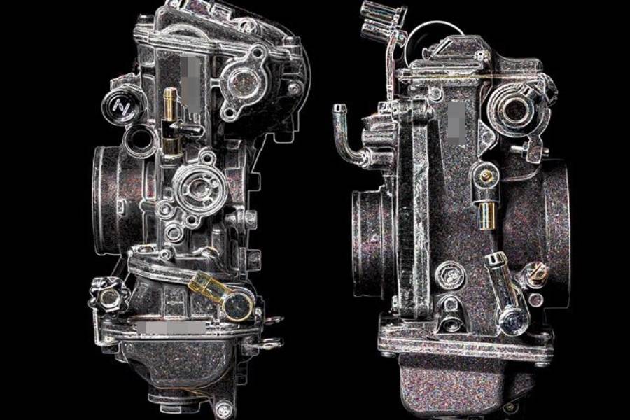
What Does a Mikuni Carburetor Diagram Show?
A Mikuni carburetor diagram shows the internal layout, component locations, and fuel-metering systems of a Mikuni carburetor. It identifies essential parts such as the float bowl, main jet, pilot jet, jet needle, throttle slide, and adjustment screws. Motorcycle owners and mechanics use these diagrams to identify components, understand their functions, and locate parts during maintenance or repair.
Mikuni carburetor diagrams are available in three main formats: labeled parts diagrams, exploded-view diagrams, and fuel circuit diagrams. Each format provides different technical information about the carburetor assembly.
- Labeled parts diagram: Identifies the names and positions of major components, including the throttle slide, float chamber, fuel jets, and adjustment screws. This format helps users recognize individual parts without disassembling the carburetor.
- Exploded-view diagram: Displays individual components separated from their assembled positions. Numbered callouts connect each part to a corresponding parts list, helping mechanics identify replacement components and understand assembly relationships.
- Fuel circuit diagram: Illustrates how fuel and air move through the carburetor. It identifies the pilot circuit, main fuel circuit, and other passages responsible for delivering the air-fuel mixture under different operating conditions.
The exact component arrangement depends on the Mikuni carburetor model. For example, Mikuni VM carburetors use a mechanically operated round slide, while Mikuni BST carburetors use a vacuum-operated slide controlled by a diaphragm. Their diagrams therefore show different throttle mechanisms and internal assemblies. Identifying the correct model is essential when using a diagram to locate components or select replacement parts.
What Are the Main Parts of a Mikuni Carburetor?
The main parts of a Mikuni carburetor include the float bowl, float needle, main jet, pilot jet, needle jet, jet needle, throttle slide, and adjustment screws. These components control fuel storage, fuel metering, airflow, and engine idle speed. Their arrangement varies between Mikuni VM, TM, BST, and HSR carburetor models.
The following table identifies the primary components found in common Mikuni carburetor designs and explains their functions.
| Component | Location | Primary Function |
|---|---|---|
| Float bowl | Bottom of carburetor | Stores fuel for the metering circuits |
| Float | Inside float bowl | Regulates fuel level |
| Float needle | Near fuel inlet valve seat | Controls fuel entering the float chamber |
| Main jet | Main fuel circuit, typically accessible through the float chamber | Meters fuel primarily at larger throttle openings |
| Pilot jet | Pilot fuel circuit | Meters fuel for idle and low-throttle operation |
| Needle jet | Main metering passage | Works with the jet needle to regulate fuel delivery |
| Jet needle | Attached to throttle slide or needle holder | Changes fuel-metering area as the slide moves |
| Throttle slide | Carburetor bore | Regulates airflow through the carburetor |
| Idle speed screw | Exterior of carburetor | Adjusts the throttle’s resting position or idle-control mechanism |
| Air screw | Exterior of applicable models | Adjusts air entering the pilot mixture circuit |
| Choke or enrichment mechanism | Starting circuit | Provides a richer mixture for cold starting |
These components operate as an interconnected fuel-delivery system. The float assembly maintains the fuel supply, the jets meter fuel, and the throttle mechanism controls airflow and fuel demand. Some Mikuni models use a fuel mixture screw instead of an air screw, while constant-velocity carburetors use a diaphragm-operated slide.
What Do the Main Jet and Pilot Jet Control?
The main jet controls fuel metering primarily at larger throttle openings, while the pilot jet controls fuel delivery at idle and small throttle openings. Both jets contain calibrated openings that restrict fuel flow through their respective circuits.
The pilot jet supplies fuel through the idle and progression passages when airflow through the carburetor is relatively low. As the throttle opens, the needle jet and jet needle become increasingly influential. At larger throttle openings, the main jet establishes an important limit on fuel delivery through the main circuit.
These circuits overlap rather than operating within completely separate throttle ranges. For example, a partially blocked pilot jet can cause unstable idling or hesitation during initial throttle opening, while an incorrectly sized main jet can contribute to an excessively rich or lean mixture at high throttle openings.
What Do the Float Bowl and Float Needle Do?
The float bowl stores fuel, while the float and float needle regulate the fuel level inside the carburetor. Maintaining the specified fuel level allows the metering circuits to deliver fuel consistently as engine demand changes.
Fuel enters the float chamber through the inlet valve. As the fuel level rises, the float moves upward and presses the float needle against its seat, restricting incoming fuel. When the engine consumes fuel, the level drops, allowing the inlet valve to reopen and replenish the chamber.
A worn float needle, contaminated valve seat, or incorrectly adjusted float can disrupt this process. For example, a float needle that fails to seal can allow excessive fuel into the chamber, causing overflow or an overly rich mixture. A fuel level below specification can restrict fuel delivery during higher engine demand.
How Do the Jet Needle and Throttle Slide Work?
The jet needle regulates fuel flow through the needle jet, while the throttle slide controls the airflow opening inside the carburetor. Together, these components influence the air-fuel mixture during throttle transitions and intermediate operating conditions.
In mechanically operated slide carburetors such as the Mikuni VM and TM series, opening the throttle raises the slide and its attached tapered jet needle. As the needle moves upward, its narrower section increases the available fuel-metering area between the needle and needle jet. At the same time, the larger throttle opening allows more air to enter the engine.
Jet needle diameter, taper, and clip position influence fuel delivery at different slide positions. For example, raising an adjustable jet needle by lowering its retaining clip generally enriches the mixture within the needle-controlled operating range.
Mikuni BST constant-velocity carburetors operate differently. Their throttle cable controls a butterfly valve, while intake pressure differences move a diaphragm-connected slide and jet needle. This mechanism allows slide movement to respond to engine airflow demand rather than following throttle cable movement directly.
How Does a Mikuni Carburetor Work?
A Mikuni carburetor works by using airflow and pressure differences to draw fuel into the engine’s intake air stream. Its venturi, throttle mechanism, float chamber, and fuel-metering circuits work together to regulate the air-fuel mixture according to engine operating conditions.
Air enters the carburetor through the intake opening and passes through a narrowed passage called the venturi. As air moves through this restriction, its velocity increases and static pressure decreases. The pressure difference between the venturi and the float chamber draws fuel through calibrated jets and discharge passages. Fuel mixes with the incoming air before traveling through the intake manifold into the engine.
The float system maintains the fuel level needed for consistent metering. Fuel enters the float bowl through an inlet valve controlled by the float and float needle. As the engine consumes fuel, the float drops and opens the valve to replenish the chamber. Maintaining the specified fuel level is essential because changes in fuel height affect the pressure difference responsible for fuel delivery.
Mikuni carburetors use overlapping fuel circuits to supply the engine at different throttle openings. The pilot circuit delivers fuel during idling and initial throttle opening. As airflow increases, the jet needle and needle jet progressively influence fuel delivery. At larger throttle openings, the main jet becomes a major restriction governing fuel flow through the main metering system.
For example, when a rider opens the throttle on a Mikuni VM carburetor, the throttle slide rises and increases the available airflow passage. The attached jet needle also rises, increasing the fuel-metering area within the needle jet. This coordinated movement allows the carburetor to deliver more air and fuel as engine demand increases. Actual mixture delivery also depends on engine speed, intake pressure, and the calibration of individual fuel circuits.
How Do Mikuni Carburetor Diagrams Differ by Model?
Mikuni carburetor diagrams differ by model because each carburetor series uses specific throttle mechanisms, fuel-metering components, and internal assemblies. The VM, TM, TMX, BST, and HSR series have distinct designs that affect component locations, fuel circuits, and replacement part identification.
The Mikuni VM series uses a mechanically operated round slide connected directly to the throttle cable. Its diagram typically shows a cylindrical throttle slide, jet needle, needle jet, main jet, pilot jet, float assembly, and idle adjustment components. The relatively straightforward construction makes VM diagrams useful for identifying individual fuel-metering parts and understanding their assembly relationships.
Mikuni TM and TMX carburetors use flat-slide designs instead of the VM series’ round slide. The flat-slide mechanism changes the throttle valve geometry and airflow characteristics. TMX models also incorporate design features intended for high-performance two-stroke applications. Their exploded-view diagrams therefore contain slide assemblies, fuel-metering components, and model-specific parts that differ from those used in VM carburetors.
Mikuni BST carburetors use a constant-velocity mechanism, while HSR carburetors use a mechanically operated flat slide with an accelerator pump. A BST diagram includes a diaphragm, vacuum chamber, throttle butterfly, and vacuum-operated slide. An HSR diagram includes an accelerator pump assembly, pump diaphragm, and fuel discharge components that provide additional fuel during rapid throttle opening.
The following table summarizes the main differences between common Mikuni carburetor families.
| Mikuni Series | Throttle Mechanism | Distinctive Diagram Components |
|---|---|---|
| VM | Mechanical round slide | Round slide, jet needle, pilot and main jets |
| TM | Mechanical flat slide | Flat-slide assembly, needle system, fuel jets |
| TMX | Mechanical flat slide | Model-specific flat-slide and fuel-metering assemblies |
| BST | Vacuum-operated slide | Diaphragm, vacuum chamber, throttle butterfly |
| HSR | Mechanical flat slide | Flat-slide assembly, accelerator pump, pump diaphragm |
Carburetor parts are not automatically interchangeable between Mikuni series or even between different models within the same series. For example, a VM carburetor diagram cannot reliably identify the diaphragm assembly of a BST carburetor or the accelerator pump components of an HSR carburetor. Mechanics should verify the complete model designation and corresponding parts diagram before ordering replacement components or disassembling the carburetor.
How Do You Read a Mikuni Carburetor Exploded View Diagram?
To read a Mikuni carburetor exploded view diagram, identify the carburetor model, locate the numbered components, and match each number with its corresponding parts list. An exploded view separates the carburetor into individual components, showing their relative positions and how they fit into the complete assembly.
Start by identifying the main carburetor body, which serves as the central reference point. Components above the body generally include the throttle slide, jet needle, return spring, and top cover in mechanically operated slide carburetors. Components below the body typically include the float bowl, float assembly, main jet, pilot jet, and related fuel-metering parts. The exact arrangement depends on the Mikuni model.
Each numbered callout identifies a specific component or assembly in the accompanying parts list. For example, a callout pointing to the main jet corresponds to a parts list entry containing its description and, when provided, its replacement part number. Some diagrams also identify multiple components as a single assembly, such as a float valve set containing a needle and valve seat. Callout numbers are diagram references, not universal Mikuni part numbers.
Exploded-view diagrams also help identify the relationship between components during inspection and reassembly. For example, the float needle must align with its valve seat, while the jet needle passes through the needle jet when the throttle slide is installed. However, an exploded view does not necessarily show the correct disassembly sequence or installation orientation. Mechanics should consult the model-specific service instructions for procedures, torque specifications, and adjustment settings.
Before purchasing replacement parts, compare the diagram’s model designation, component description, and manufacturer part number with the installed carburetor. Two Mikuni carburetors with similar external appearances can use different jets, needles, gaskets, and float assemblies. Matching the exact model and component specifications helps prevent incorrect parts selection and assembly problems.
How Can a Mikuni Carburetor Diagram Help Identify Common Problems?
A Mikuni carburetor diagram helps identify common problems by showing the components responsible for fuel delivery, idle control, and throttle response. Mechanics can use the diagram to locate the fuel circuits and assemblies associated with symptoms such as rough idling, fuel overflow, poor acceleration, and engine hesitation.
Carburetor problems frequently involve restricted fuel passages, incorrect fuel levels, worn components, or improper adjustments. For example, a blocked pilot jet can restrict fuel delivery at idle, while a float needle that fails to seal can cause excessive fuel to enter the float chamber. A labeled diagram identifies these components and shows their positions within the carburetor assembly.
The following table connects common operating symptoms with the Mikuni carburetor components that should be inspected.
| Symptom | Components to Inspect | Possible Cause |
|---|---|---|
| Rough or unstable idle | Pilot jet, idle mixture screw, idle passages | Blocked pilot circuit or incorrect adjustment |
| Fuel leaking from overflow | Float, float needle, valve seat | Incorrect fuel level or inlet valve failing to seal |
| Hesitation during acceleration | Jet needle, needle jet, pilot circuit | Incorrect fuel metering or restricted passages |
| Poor performance at large throttle openings | Main jet, fuel inlet, float system | Restricted fuel supply or incorrect jet calibration |
| Difficult cold starting | Choke or enrichment circuit, pilot jet | Insufficient starting enrichment or restricted fuel passages |
A carburetor diagram identifies inspection points but does not confirm the cause of an engine problem. Similar symptoms can result from intake air leaks, ignition faults, incorrect valve clearances, or fuel supply restrictions outside the carburetor. Diagnosis requires checking the relevant components and verifying their condition against the manufacturer’s specifications.
Which Mikuni Carburetor Parts Should You Check First?
The first Mikuni carburetor parts to inspect depend on the operating symptom and the throttle position at which it occurs. Begin with the components associated with the affected fuel circuit rather than disassembling the entire carburetor.
For unstable idling, inspect the pilot jet, pilot air passages, and idle adjustment settings. For fuel overflow, examine the float needle, valve seat, float movement, and specified fuel level. For hesitation during throttle opening, check the pilot circuit and needle system before considering changes to jet calibration.
For example, a motorcycle that idles normally but loses power at larger throttle openings may have a restricted main jet or insufficient fuel entering the float chamber. The carburetor diagram helps locate these components for inspection. Confirming the cause also requires checking fuel flow, component condition, and the specifications for the exact Mikuni model.
Before removing the float bowl or fuel-system components, shut off the fuel supply, allow the engine to cool, and work in a well-ventilated area away from ignition sources. Use the correct service documentation to avoid damaging calibrated jets, sealing surfaces, and adjustment mechanisms.
Read more: Briggs and Stratton Carb Diagram: Parts & Functions
How Do You Identify the Correct Mikuni Carburetor Diagram?
To identify the correct Mikuni carburetor diagram, locate the carburetor’s model markings and match them with the corresponding manufacturer parts documentation. The model designation determines which internal components, fuel circuits, and replacement parts appear in the diagram.
Start by inspecting the carburetor body for identification numbers, letters, or stamped markings. Depending on the model, these markings may appear on the side of the carburetor body, near the mounting flange, or around the float chamber. Common Mikuni series include VM, TM, TMX, BST, and HSR, although individual models and OEM-specific versions have additional identification details.
Carburetor diameter alone is insufficient for identifying the correct parts diagram. For example, two Mikuni carburetors with the same nominal bore diameter can use different throttle slides, jet needles, float assemblies, and fuel-metering components. The complete model designation and application specifications are necessary for accurate identification.
Motorcycle manufacturer parts catalogs provide another identification method, particularly for factory-installed Mikuni carburetors. OEM versions may contain components and calibration settings that differ from aftermarket carburetors within the same general series. Comparing the motorcycle’s make, model, production year, and carburetor identification markings helps narrow down the correct documentation.
Before using an exploded-view diagram for repairs, verify that its component arrangement matches the installed carburetor. Check distinctive features such as the throttle mechanism, float bowl design, enrichment system, and adjustment screw locations. If identification markings are missing or unclear, consult the appropriate manufacturer or authorized Mikuni distributor before selecting replacement parts.
Where Can You Find Mikuni Carburetor Parts Diagrams?
Mikuni carburetor parts diagrams are available through authorized Mikuni distributors, manufacturer technical documentation, motorcycle OEM parts catalogs, and model-specific service manuals. These sources provide exploded-view illustrations, component descriptions, and part numbers needed for accurate identification and replacement.
Authorized Mikuni distributors are useful sources for aftermarket carburetor diagrams, particularly for common VM, TM, and HSR models. Their technical catalogs may include numbered exploded views, replacement parts lists, and specifications for jets, needles, float assemblies, and gaskets. The official Mikuni American website at mikuni.com is a starting point for locating product information and distributor resources.
Motorcycle OEM parts catalogs are generally the preferred reference for factory-installed Mikuni carburetors. Manufacturers such as Yamaha, Suzuki, and Kawasaki have used Mikuni carburetors in various motorcycle models. Their parts catalogs identify components according to the vehicle’s model and production year, helping distinguish OEM-specific assemblies from aftermarket versions.
Service manuals provide additional information that exploded-view diagrams do not show, including disassembly procedures, float-level specifications, adjustment settings, and inspection methods. For example, a parts diagram identifies the float needle and valve seat, while the corresponding service manual explains how to inspect the assembly and verify the specified fuel level.
Always match the diagram to the carburetor’s complete model designation before ordering parts. A visually similar diagram does not guarantee component compatibility, especially when comparing different Mikuni series or OEM-specific carburetor configurations.