The 700R4 check ball locations are found within the transmission’s hydraulic control assembly, with check balls positioned in designated passages associated with the valve body, separator plate, and transmission case. These small steel balls regulate automatic transmission fluid (ATF) flow through specific hydraulic circuits, helping control pressure distribution and gear engagement. Correct placement is essential because a missing or incorrectly positioned check ball can alter hydraulic operation and cause shifting problems.
The number and placement of check balls in a 700R4 transmission depend on its production configuration, valve body design, and any aftermarket modifications. Although the 700R4 was later designated the 4L60, not every transmission assembly uses an identical check ball arrangement. Rebuild kits and shift kits may also specify different configurations, making it important to identify the correct layout before installation.
This guide explains where 700R4 check balls are located, how to identify the appropriate placement diagram, and what to check during valve body assembly. It also covers check ball functions, common installation mistakes, and transmission symptoms associated with incorrect placement. Before installing the check balls, verify the transmission configuration against the applicable service documentation or shift kit instructions to prevent assembly errors.
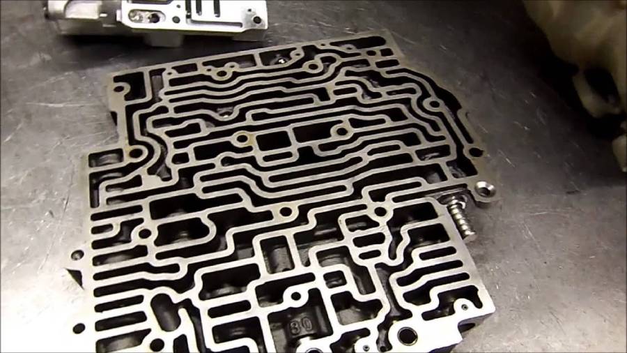
Where Are the Check Balls Located in a 700R4 Transmission?
The 700R4 check balls are positioned in designated hydraulic passages within the valve body and transmission case, depending on the transmission’s configuration. These locations work with the separator plate to control automatic transmission fluid (ATF) flow during gear changes. Each check ball sits in a specific passage or seat, where hydraulic pressure moves it to open or restrict fluid flow.
The correct placement depends on the valve body design, separator plate configuration, and any modifications made during previous repairs. A check ball location diagram identifies the required positions relative to the hydraulic passages and mounting surfaces. The diagram must also show the viewing orientation because the valve body and transmission case expose different sides of the hydraulic assembly.
Where Do the Check Balls Go in the 700R4 Valve Body?
The 700R4 valve body check balls occupy designated hydraulic passage locations associated with the valve body and separator plate assembly. Their positions allow fluid pressure to act on individual check balls as the transmission changes operating conditions. Each ball functions within a specific hydraulic circuit rather than serving as a general seal between the valve body and separator plate.
Check ball positions are identified by examining the valve body’s hydraulic passages and matching them to the applicable separator plate layout. The valve body contains channels that distribute transmission fluid to shift valves, accumulators, and other hydraulic components. Check balls control flow through selected passages, affecting how pressure reaches these components during transmission operation.
Not every circular recess or passage opening is intended to hold a check ball. Some openings serve as fluid transfer passages, bolt holes, or other hydraulic features. Installing a ball in an unspecified location can obstruct fluid flow, while omitting a required ball can leave a passage unrestricted. The correct service diagram must therefore determine placement rather than the appearance of an individual recess.
Where Are the Check Balls Located in the 700R4 Transmission Case?
Case-side check ball locations are found in specified hydraulic passages on the transmission case mating surface, where required by the particular 700R4 configuration. These passages connect the transmission case to the valve body assembly through the separator plate and gaskets. Their arrangement supports hydraulic communication between the control system and internal transmission components.
The transmission case contains fluid passages that connect hydraulic circuits to components such as accumulators and clutch-related circuits. A check ball installed in a designated case passage controls fluid movement according to the pressure conditions within that circuit. Its position must correspond to the correct separator plate opening to maintain the intended hydraulic operation.
To identify case-side locations, examine the exposed transmission case with the valve body removed and compare its passage arrangement with the applicable service diagram. Confirm the diagram’s orientation using identifiable mounting holes, fluid passages, and component locations. Do not assume that a check ball position shown on the valve body side corresponds to the same visible position when viewing the transmission case.
The final placement must match the transmission’s actual valve body, separator plate, and modification history. A diagram from another production configuration or aftermarket shift kit should not be used without confirming compatibility.
How Many Check Balls Are in a 700R4 Transmission?
A stock 700R4 transmission commonly uses seven check balls, although the required number depends on the valve body configuration, production revisions, and aftermarket modifications. The check balls operate within specific hydraulic circuits, and their placement is determined by the transmission’s separator plate and valve body design. The correct count must be verified against the service documentation for the particular assembly before installation.
The number of check balls found during disassembly does not always indicate the correct factory configuration. Previous repairs, replacement valve bodies, and aftermarket shift kits may change the required arrangement. Some shift improvement kits instruct technicians to omit specific check balls to modify hydraulic flow and shift characteristics. These changes must follow the manufacturer’s instructions because removing a check ball without an approved modification can disrupt the transmission’s hydraulic operation.
Counting the check balls is only the first step in verifying correct installation. Each required ball must occupy its designated position, and an empty passage does not necessarily indicate a missing component. For example, a transmission modified with an aftermarket shift kit may have fewer installed check balls than its original configuration. Matching the check ball count to the correct placement diagram helps prevent incorrect assembly.
Do 700R4 Check Ball Locations Vary by Model Year?
700R4 check ball locations can vary between production configurations, particularly when changes to the valve body, separator plate, or hydraulic control circuits affect the required arrangement. General Motors introduced the 700R4 for the 1982 model year and made multiple design revisions throughout its production history. The transmission was renamed the 4L60 for the 1990 model year, retaining hydraulic control before the introduction of the electronically controlled 4L60E.
Production changes affected several internal transmission components, including valve body assemblies and hydraulic control systems. These differences make it necessary to verify the applicable check ball layout instead of assuming that a diagram from another model year will match. A replacement valve body or separator plate can also introduce configuration differences even when the transmission case remains original.
The correct diagram should be selected using the transmission identification information and the physical characteristics of the installed components. Examine the valve body casting, separator plate passage pattern, and available identification markings. Compare these details with the appropriate General Motors service documentation or the instructions supplied with the rebuild kit. If the transmission contains an aftermarket shift kit, its installation instructions take priority for the specific modifications included in that kit.
Model year alone is not sufficient to establish check ball placement when internal components have been replaced. For example, a 1987 transmission fitted with a replacement valve body may require a different verification process than an untouched factory assembly. Identifying the actual components ensures that each check ball corresponds to the intended hydraulic passage and helps prevent shifting problems after reassembly.
How Do You Install Check Balls in a 700R4 Transmission?
To install check balls in a 700R4 transmission, identify the correct valve body configuration, inspect the hydraulic components, place each check ball in its designated location, and verify the arrangement before reassembly. The installation process requires accurate positioning because check balls regulate transmission fluid flow through specific hydraulic circuits. Incorrect placement can interfere with pressure distribution and cause abnormal shifting.
The installation procedure involves five main steps: identifying the transmission configuration, inspecting the components, positioning the check balls, aligning the separator plate and gaskets, and verifying the assembly. Each step must follow the applicable General Motors service documentation or aftermarket shift kit instructions.
What Should You Check Before Installing 700R4 Check Balls?
Before installing 700R4 check balls, verify the transmission configuration, check ball specifications, valve body condition, and separator plate alignment. These inspections help identify damaged components and prevent installation errors that could affect hydraulic operation.
First, identify the transmission’s production configuration and inspect the installed valve body and separator plate. Compare their identification markings and passage patterns with the appropriate service documentation. Check for evidence of aftermarket modifications, including enlarged separator plate openings or components supplied with a shift improvement kit. Modified transmissions may require a different check ball arrangement from the original factory configuration.
Second, inspect each check ball for surface damage, corrosion, deformation, or excessive wear. A serviceable check ball should have a smooth, undamaged surface that allows it to seat correctly against its hydraulic passage. Verify the required diameter and material against the applicable parts specifications. Do not substitute a different check ball simply because it fits inside the passage.
Third, examine the separator plate and valve body for damaged passages, worn check ball seats, contamination, and gasket residue. Repeated contact between a check ball and its seating surface can cause wear, particularly around separator plate openings. A damaged opening may allow the ball to seat incorrectly or interfere with the intended hydraulic restriction. Replace or repair affected components according to the relevant service procedure.
How Do You Verify Check Ball Placement Before Reinstalling the Valve Body?
To verify 700R4 check ball placement, compare every installed ball with the correct location diagram, confirm the required count, and inspect the separator plate and gasket alignment. Complete this inspection before securing the valve body because correcting a misplaced check ball afterward requires disassembly.
Begin by placing each check ball into the location specified by the applicable diagram. Use the diagram’s viewing orientation to distinguish valve body positions from transmission case positions. When the service procedure permits it, a small amount of suitable assembly lubricant can help retain a check ball during installation. Avoid excessive lubricant or any material that could obstruct hydraulic passages.
Next, count the installed check balls and compare their positions with the documented configuration. Inspect each designated location individually rather than relying only on the total number. A transmission containing the correct number of check balls can still malfunction if one ball occupies an incorrect passage. Confirm that no additional balls remain on the workbench or inside an unintended recess.
Inspect the separator plate and gaskets before final assembly. The separator plate must match the valve body configuration, and the gaskets must align with the intended hydraulic passages. Incorrect gasket orientation can block a required fluid passage or create an unintended connection between circuits. Use the specified gasket identification and alignment features rather than assuming that visually similar gaskets are interchangeable.
Finally, position the valve body carefully to prevent check balls from moving out of their seats. Install the mounting fasteners according to the applicable service procedure and tighten them in the specified sequence using the correct torque values. Avoid guessing torque specifications because excessive tightening can damage components, while insufficient tightening can compromise hydraulic sealing.
After completing the valve body installation, finish transmission reassembly according to the service manual. Refill the transmission with the specified automatic transmission fluid, verify the fluid level using the correct temperature and operating procedure, and inspect for leaks. Confirm normal transmission operation before returning the vehicle to regular service. Any abnormal shifting after assembly requires further diagnosis rather than assuming the check balls were installed correctly.
What Do Check Balls Do in a 700R4 Transmission?
Check balls in a 700R4 transmission control hydraulic fluid flow by opening or restricting specific passages within the valve body and transmission case. They function as hydraulic check valves, allowing transmission fluid to move through designated circuits while restricting reverse flow or directing pressure through alternative passages. Their operation contributes to the timing and control of automatic gear changes.
Each check ball responds to pressure differences within its hydraulic circuit. When fluid pressure acts against the ball in the permitted direction, the ball moves away from its seat and allows fluid to pass. When pressure acts in the opposite direction, the ball moves against its seat and restricts the passage. The surrounding valve body channels and separator plate openings determine how this movement affects fluid distribution.
Check balls also influence the rate at which hydraulic pressure builds or releases in certain transmission circuits. For example, a check ball can allow fluid to bypass a calibrated restriction in one direction while directing fluid through that restriction in the opposite direction. This arrangement helps control the timing of clutch or band application and release during gear changes.
The function of each check ball depends on its assigned hydraulic passage. Moving a ball to another location can change the intended flow path, even when the replacement position appears physically similar. Correct placement preserves the hydraulic circuit arrangement established by the transmission’s valve body and separator plate configuration.
What Happens If 700R4 Check Balls Are Installed Incorrectly?
Incorrectly installed 700R4 check balls can cause delayed shifting, harsh gear engagement, slipping, or failure to engage certain gears. These problems occur when a misplaced or missing check ball changes hydraulic fluid flow through a circuit responsible for transmission operation. The specific symptoms depend on which passage is affected and how the resulting pressure change influences the associated components.
A missing check ball can leave a hydraulic passage open when it should restrict fluid movement. This may prevent a circuit from developing or maintaining the pressure required for proper operation. For example, unintended fluid flow through a clutch-related circuit can interfere with engagement timing and contribute to slipping or delayed gear changes.
An incorrectly positioned check ball can also obstruct a passage that must remain open. Restricted fluid flow may change the timing of hydraulic pressure application or release, resulting in abnormal shift characteristics. Depending on the affected circuit, the transmission may exhibit unusually firm shifts, delayed engagement, or inconsistent operation between gears.
Incorrect check ball placement is not the only cause of these symptoms. Worn clutch components, damaged seals, sticking shift valves, incorrect throttle valve cable adjustment, and hydraulic pressure problems can produce similar behavior. When shifting problems appear after valve body service, check ball placement should be verified alongside separator plate alignment, gasket installation, and other components disturbed during the repair.
Continued operation with an unresolved hydraulic fault can increase wear on transmission components. If abnormal shifting begins immediately after reassembly, inspect the installation against the correct service documentation before performing further road testing. Hydraulic pressure testing and additional diagnosis may be necessary when the check ball arrangement is correct but the symptoms remain.
What Are the Most Common 700R4 Check Ball Installation Mistakes?
The five most common 700R4 check ball installation mistakes involve using the wrong placement diagram, installing an incorrect number of balls, selecting the wrong hydraulic passages, misaligning the separator plate, and overlooking aftermarket modifications. These errors can alter transmission fluid flow and affect shifting performance after valve body reassembly.
1. Using the wrong check ball location diagram. A placement diagram must match the installed valve body and separator plate configuration. Using instructions intended for a different assembly can result in check balls being installed in incorrect passages. Verify the transmission identification and hydraulic component configuration before following a diagram.
2. Installing the wrong number of check balls. Missing or additional check balls can change the intended hydraulic circuit operation. A missing ball may allow unrestricted fluid movement, while an extra ball may obstruct a passage. Compare the installed quantity and individual locations with the applicable service documentation rather than relying on a general check ball count.
3. Placing check balls in incorrect hydraulic passages. Several valve body recesses and fluid openings can appear similar during assembly. However, only designated locations require check balls. Installing a ball in the wrong passage can interrupt hydraulic communication or change pressure distribution. Identify each seating location using the correct diagram and its specified viewing orientation.
4. Misaligning the separator plate or valve body gaskets. Incorrect alignment can obstruct hydraulic passages or create unintended connections between circuits. This problem may produce symptoms similar to incorrect check ball placement. Confirm the separator plate orientation, gasket identification, and fluid passage alignment before tightening the valve body fasteners.
5. Ignoring aftermarket shift kit modifications. Some shift kits modify hydraulic flow by changing separator plate openings or specifying different check ball arrangements. Reinstalling every ball according to a factory diagram can conflict with these modifications. Follow the instructions for the installed shift kit and verify that its components match the transmission configuration.
Preventing these mistakes requires documenting the original assembly, identifying replacement components, and checking every specified ball location before installation. Photographs taken during disassembly provide useful references, but the correct service documentation remains the primary source for verifying placement.
Read more: G37 Valve Body Replacement: Cost, Symptoms & Steps
How Can You Tell If 700R4 Check Balls Need Replacement?
700R4 check balls need replacement when inspection reveals surface damage, deformation, corrosion, or wear that prevents proper seating in their hydraulic passages. A damaged check ball may fail to restrict fluid flow as intended, allowing pressure leakage or interfering with hydraulic circuit operation. Inspection should include both the check balls and their corresponding seating surfaces.
Start by cleaning the removed check balls with an appropriate transmission-component cleaning method and examining their surfaces under adequate lighting. Look for flat spots, pitting, scratches, or visible deformation. A check ball should retain the spherical shape and surface condition specified for its application. Any ball showing damage outside the applicable service limits should be replaced with the correct specification.
Inspect the separator plate openings and valve body seating surfaces for wear. Repeated contact between a check ball and its seat can produce indentation or deformation around the passage. A damaged seat may prevent proper sealing even when the check ball itself remains in good condition. Replacing the ball alone will not correct a worn or enlarged seating surface.
Check ball material and diameter must also match the transmission’s specifications. Some aftermarket repair kits include replacement balls or modified components intended for particular hydraulic configurations. Do not assume that all check balls supplied with different rebuild kits are interchangeable. Verify the required specifications before installing replacement parts.
Replacement decisions should be based on physical inspection, component specifications, and the applicable repair instructions rather than shifting symptoms alone. Delayed engagement, slipping, and harsh shifts can also result from worn seals, valve body problems, or incorrect hydraulic pressure. When check balls and their seats show no defects, further diagnosis is necessary to identify the source of the transmission problem.
Are 700R4 and 4L60 Check Ball Locations the Same?
700R4 and hydraulically controlled 4L60 transmissions share the same basic design, but their check ball locations should not be assumed identical across every production configuration. General Motors renamed the 700R4 transmission to 4L60 for the 1990 model year, following its transmission naming convention. The name change did not introduce an entirely new hydraulic control system, although production revisions and component differences can affect the correct check ball arrangement.
Both transmissions use check balls within their hydraulic control assemblies to regulate automatic transmission fluid flow. Their valve bodies, separator plates, and hydraulic passages perform similar functions in controlling gear engagement and shift timing. However, compatibility between individual components depends on the specific production version and installed hardware rather than the transmission designation alone.
The main differences to examine are the valve body configuration, separator plate passage pattern, and any modifications made during previous repairs. A 700R4 and an early 4L60 may have compatible check ball arrangements when their hydraulic components match. Conversely, installing a replacement valve body or aftermarket shift kit can change the required placement, even within transmissions carrying the same designation.
The electronically controlled 4L60E requires separate consideration. Introduced for the 1993 model year, the 4L60E uses electronic shift control and has valve body and hydraulic system differences from the hydraulically controlled 700R4 and 4L60. A 4L60E check ball diagram should not be used as a direct installation reference for a 700R4 without verified component compatibility.
To determine whether two check ball diagrams are interchangeable, compare the transmission identification, valve body casting, separator plate configuration, and applicable service documentation. Confirm that each designated check ball position corresponds to the same hydraulic circuit. Matching the physical components and their intended fluid passages provides a more reliable installation reference than relying on transmission names or model years alone.