A Walbro carb diagram shows the internal components, fuel passages, diaphragms, valves, and adjustment mechanisms of a Walbro carburetor. It helps identify individual parts, understand how fuel moves through the carburetor, and locate components that require inspection, cleaning, or replacement. The exact arrangement depends on the carburetor model, making model identification essential before using a diagram for repairs.
Walbro carburetors are commonly used in small gasoline engines, including those powering chainsaws, string trimmers, leaf blowers, and other outdoor equipment. Many models use a diaphragm-operated fuel system that regulates fuel delivery without relying on a conventional float bowl. Key components include the fuel pump diaphragm, metering diaphragm, inlet needle, metering lever, throttle plate, and fuel adjustment screws. Each component performs a specific function in controlling fuel delivery and the air-fuel mixture.
This guide explains how to read a Walbro carburetor diagram, identify its main parts, and understand their functions. It also covers fuel flow, adjustment screw locations, differences between Walbro carburetor models, and how to use exploded parts diagrams for troubleshooting and reassembly.
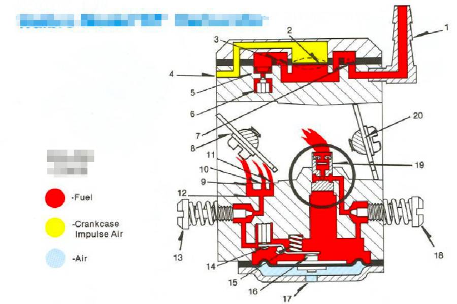
What Does a Walbro Carburetor Diagram Show?
A Walbro carburetor diagram shows the location, arrangement, and connections of the components responsible for fuel delivery and air-fuel mixture control. It identifies parts such as the fuel pump diaphragm, metering diaphragm, inlet needle, throttle plate, choke plate, and adjustment screws. The diagram helps mechanics locate individual components and understand their relationships before inspecting, disassembling, or repairing the carburetor.
Walbro carburetor diagrams generally serve three purposes: parts identification, assembly reference, and fuel system analysis. A labeled parts diagram identifies components by name or reference number, while an exploded diagram separates components to illustrate their assembly positions. A fuel flow diagram shows how gasoline travels through internal passages before entering the engine’s intake airflow. Each diagram provides different information, so selecting the correct type depends on the maintenance task.
The diagram must also match the carburetor’s specific model number. Walbro manufactures several carburetor series, including WT, WA, WYK, and WYL, with differences in component configurations, fuel circuits, and adjustment mechanisms. For example, a diagram for one WT model should not automatically be used to determine the gasket arrangement or replacement parts for a WYK carburetor. Matching the model number ensures that the illustrated components correspond to the actual carburetor.
What Are the Main Parts of a Walbro Carburetor?
The main parts of a typical Walbro diaphragm carburetor include the carburetor body, fuel pump diaphragm, metering diaphragm, inlet needle, metering lever, throttle plate, choke plate, fuel passages, and adjustment mechanisms. These components work together to draw fuel from the tank, regulate fuel delivery, and supply the engine with an appropriate air-fuel mixture. Their exact configuration varies by model and application.
| Component | Primary function |
|---|---|
| Carburetor body | Houses the internal fuel and air passages |
| Fuel pump diaphragm | Pumps fuel using engine pressure pulses |
| Metering diaphragm | Responds to pressure changes to regulate fuel supply |
| Inlet needle | Opens or closes the fuel inlet to the metering chamber |
| Metering lever | Transfers diaphragm movement to the inlet needle |
| Throttle plate | Controls airflow and engine power |
| Choke plate | Restricts incoming air during cold starting |
| Inlet screen | Filters debris from incoming fuel |
| Adjustment screws | Regulate applicable fuel circuits and idle speed |
| Gaskets | Seal carburetor chambers and mating surfaces |
The carburetor body contains the venturi, where incoming air accelerates through a narrowed passage. This airflow creates a pressure difference that draws fuel from calibrated discharge openings into the intake stream. The throttle plate regulates the amount of air-fuel mixture entering the engine, while the choke plate enriches the mixture during cold starting by restricting incoming air. These mechanisms operate alongside the diaphragm-controlled fuel system.
What Does the Metering Diaphragm Do in a Walbro Carburetor?
The metering diaphragm regulates fuel admission into the metering chamber by responding to pressure changes within the carburetor. It works with the metering lever, inlet needle, and spring to maintain an appropriate fuel supply as engine demand changes. Unlike a conventional float-type carburetor, a diaphragm carburetor does not depend on a float and fuel bowl to control its fuel level.
When pressure in the metering chamber decreases, the diaphragm moves toward the metering lever. This movement pushes the lever, lifting the inlet needle from its seat and allowing fuel to enter the chamber. As chamber pressure recovers, the spring and diaphragm mechanism allow the inlet needle to close. This process regulates fuel admission while the engine operates at different speeds and throttle positions.
A damaged, hardened, or incorrectly installed metering diaphragm can interfere with this regulation. For example, a stiff diaphragm may fail to move the metering lever sufficiently, restricting fuel delivery and contributing to difficult starting or poor acceleration. The diaphragm must match the carburetor model and be installed with the correct gasket arrangement.
How Does the Fuel Pump Diaphragm Work?
The fuel pump diaphragm uses alternating pressure pulses from the engine crankcase to move fuel from the tank into the carburetor’s fuel system. These pulses flex a thin diaphragm inside the fuel pump chamber, creating the pressure changes needed to draw in and discharge fuel. This design allows compatible diaphragm carburetors to operate in different orientations without a gravity-dependent float bowl.
During the suction phase, diaphragm movement increases the pump chamber volume and draws fuel through the inlet check valve. During the discharge phase, the diaphragm moves in the opposite direction, reducing chamber volume and forcing fuel through the outlet check valve. The check valves maintain one-way fuel movement toward the metering system.
Fuel pump performance depends on diaphragm flexibility, check valve sealing, and the integrity of the pulse passage. A torn diaphragm, obstructed pulse channel, or leaking check valve can reduce fuel delivery. For example, an engine that starts briefly but stalls as fuel demand increases may have insufficient fuel supply caused by a faulty pump diaphragm, although fuel lines, filters, and other components must also be checked before confirming the cause.
How Does Fuel Flow Through a Walbro Carburetor?
Fuel flows through a typical Walbro diaphragm carburetor in five main stages: fuel inlet, fuel pump chamber, inlet needle, metering chamber, and fuel discharge passages. The fuel pump draws gasoline from the tank, while the metering system regulates how much fuel enters the carburetor’s internal circuits. Fuel then mixes with incoming air before the mixture travels into the engine’s intake system.
The process begins when pressure pulses from the engine crankcase activate the fuel pump diaphragm. As the diaphragm flexes, it creates alternating suction and pressure inside the pump chamber. Inlet and outlet check valves direct fuel movement, preventing gasoline from flowing backward during each pumping cycle. Fuel passes through the inlet screen, which traps debris before it reaches sensitive internal passages. The precise position of the screen within the fuel circuit depends on the carburetor model.
After leaving the pump circuit, fuel reaches the inlet needle controlled by the metering lever and metering diaphragm. When pressure in the metering chamber decreases, diaphragm movement opens the inlet needle, allowing additional fuel to enter. As pressure recovers, the needle closes to regulate fuel admission. This mechanism maintains fuel availability without the float bowl used in conventional carburetors.
Fuel leaves the metering chamber through calibrated low-speed and high-speed circuits, depending on throttle position and engine operating conditions. At low throttle openings, the idle and progression ports supply fuel near the throttle plate. As airflow increases through the venturi, the main discharge circuit supplies additional fuel. The pressure difference between the fuel passages and intake airflow draws gasoline into the air stream, forming the combustible mixture delivered to the engine.
The fuel flow diagram also helps identify restrictions that interfere with engine operation. For example, a blocked inlet screen can limit fuel delivery before gasoline reaches the metering chamber, while an obstructed main discharge passage can affect operation at higher throttle openings. Following the fuel path from the inlet to the discharge ports helps isolate the section requiring inspection.
Where Are the Adjustment Screws on a Walbro Carburetor?
Walbro carburetor adjustment screws are generally located on the exterior of the carburetor body, with their positions and functions determined by the specific model. Adjustable models may have three primary controls: a high-speed mixture screw marked H, a low-speed mixture screw marked L, and an idle speed screw commonly marked T, LA, or another model-specific designation. Some Walbro carburetors use fixed fuel jets or limiter-equipped adjustments instead of conventional H and L screws.
The high-speed adjustment screw (H) regulates fuel flow through the adjustable high-speed circuit, influencing the air-fuel mixture during higher engine speeds and throttle openings. Turning the screw clockwise generally reduces fuel flow in conventional needle-type designs, producing a leaner mixture, while turning it counterclockwise increases fuel flow. Incorrect adjustment can cause poor acceleration, excessive fuel consumption, or overheating. A mixture that is too lean is particularly dangerous for two-stroke engines because it can increase operating temperature and contribute to engine damage.
The low-speed adjustment screw (L) controls fuel delivery through the adjustable low-speed circuit, affecting idle mixture quality, throttle response, and the transition from idle to higher engine speeds. An incorrect low-speed setting can cause hesitation, unstable idling, or stalling when the throttle opens. The low-speed circuit also interacts with the main fuel circuit during throttle transitions, making its adjustment important for smooth engine operation.
The idle speed screw adjusts the throttle stop position rather than directly controlling fuel mixture. Turning it clockwise on many conventional designs opens the throttle plate slightly farther, increasing idle speed, while turning it counterclockwise reduces the throttle opening. On chainsaws and other equipment with moving cutting attachments, excessive idle speed can create a safety hazard by causing the attachment to move while the engine is idling.
Adjustment procedures must follow the specifications for the exact Walbro carburetor and engine combination. Screw locations, adjustment ranges, limiter caps, and factory settings differ between models. Before making adjustments, identify the carburetor model, inspect the air filter and fuel system, and consult the appropriate service instructions. Do not assume that a generic screw-turn setting applies to every Walbro carburetor.
How Do Walbro Carburetor Diagrams Differ by Model?
Walbro carburetor diagrams differ by model in component arrangement, fuel passage design, diaphragm configuration, adjustment mechanisms, and replacement part numbers. Although Walbro WT, WA, WYK, and WYL carburetors share diaphragm-based fuel metering principles, their internal layouts are not interchangeable. Each model has a specific parts diagram that identifies its components, assembly positions, and compatible replacement parts.
The differences become apparent when comparing exploded diagrams from separate carburetor series. Fuel pump covers, metering chambers, throttle shafts, choke mechanisms, and adjustment screws can occupy different positions depending on the carburetor design. Some models feature externally adjustable high-speed and low-speed fuel circuits, while others use fixed jets or restricted adjustment systems. Even carburetors belonging to the same series may require different diaphragms, gaskets, or inlet needles.
The following table summarizes the main considerations when comparing Walbro carburetor diagrams.
| Carburetor series | Diagram characteristics |
|---|---|
| Walbro WT | Diaphragm carburetor designs with model-specific fuel circuits, covers, and adjustment configurations |
| Walbro WA | Diaphragm carburetor designs with component layouts and replacement parts that vary by model |
| Walbro WYK | Carburetor configurations that require model-specific identification of fuel metering and adjustment components |
| Walbro WYL | Diaphragm carburetor designs with model-dependent internal passages, covers, and service components |
A diagram should always be selected using the complete carburetor model number rather than the series designation alone. For example, two WT-series carburetors may have similar external appearances but different metering components or gasket specifications. Using an incorrect exploded diagram can lead to improper assembly, fuel leakage, or inconsistent engine performance.
Where Can You Find a Walbro WT Carburetor Diagram?
A Walbro WT carburetor diagram can be found in model-specific illustrated parts lists, manufacturer service documentation, and equipment manufacturer parts catalogs. The correct diagram identifies the individual components of the WT carburetor and provides reference numbers that correspond to replacement parts.
The WT series includes multiple carburetor models used in small-engine applications. Their diagrams typically illustrate the carburetor body, fuel pump diaphragm, metering diaphragm, inlet needle, metering lever, springs, gaskets, and external control components. Exploded diagrams also show the relative positions of removable parts, helping technicians identify components during disassembly and reassembly.
To locate the correct WT diagram, first identify the complete model designation stamped or marked on the carburetor body. Search for that designation together with terms such as “parts diagram,” “exploded view,” or “illustrated parts list.” Compare the resulting diagram with the physical carburetor, paying particular attention to the fuel inlet position, throttle linkage, cover configuration, and adjustment screws.
A WT-series diagram should not be treated as a universal assembly reference for every WT carburetor. Replacement diaphragm kits, gasket arrangements, and metering components must be verified against the exact model before ordering or installing parts.
How Can You Identify Your Walbro Carburetor Model Number?
You can identify a Walbro carburetor model number by locating the stamped or engraved identification code on the carburetor body and matching it with the manufacturer’s model documentation. The marking typically contains a series designation followed by a model-specific number or additional identification characters.
Start by inspecting the exterior of the carburetor body, particularly the metal surfaces near the mounting flange, throttle mechanism, or fuel inlet. Remove loose dirt and grease with a soft brush or suitable cleaning cloth to make the identification markings easier to read. Avoid aggressive scraping that could damage stamped characters or sealing surfaces.
Once the identification code is visible, record the complete designation, including any suffixes. For example, a marking beginning with WT identifies the carburetor series, but the remaining characters are necessary to distinguish the specific model. The equipment manufacturer’s engine or product model number can provide an additional reference when confirming carburetor compatibility.
If the identification marking is missing or unreadable, compare the carburetor’s physical characteristics with manufacturer documentation. Relevant features include the fuel inlet orientation, mounting hole spacing, throttle shaft configuration, choke mechanism, and diaphragm cover design. These characteristics help narrow the identification, but visual similarity alone does not confirm that two carburetors use identical internal parts.
Correct model identification is essential when selecting a Walbro carburetor diagram, rebuild kit, or replacement component. It prevents mismatched parts and ensures that maintenance procedures follow the intended carburetor design.
How Can You Use a Walbro Carb Diagram to Troubleshoot Fuel Problems?
A Walbro carb diagram helps troubleshoot fuel problems by identifying the components and fuel passages associated with hard starting, rough idling, fuel leakage, and insufficient fuel delivery. By comparing engine symptoms with the carburetor’s internal layout, mechanics can determine which components require inspection. The diagram provides a reference for locating potential faults, but physical testing is necessary to confirm the cause.
Fuel system troubleshooting should follow the direction of fuel flow, beginning at the fuel tank and progressing through the fuel inlet, pump diaphragm, inlet screen, metering chamber, and discharge passages. Each component has a specific function, and a failure at one stage can affect fuel delivery throughout the system. For example, a restricted inlet screen reduces fuel entering the metering system, while a leaking inlet needle can allow excessive fuel into the metering chamber.
| Engine symptom | Potential carburetor component | Inspection focus |
|---|---|---|
| Hard starting | Fuel pump diaphragm, inlet needle | Diaphragm condition and fuel admission |
| Rough idling | Low-speed fuel circuit, metering diaphragm | Blocked passages and fuel regulation |
| Fuel leakage | Inlet needle, gaskets | Needle sealing and gasket damage |
| Poor acceleration | Metering lever, low-speed circuit | Fuel delivery during throttle transitions |
| High-speed power loss | Main fuel circuit, inlet screen | Fuel restrictions and delivery capacity |
| Engine flooding | Inlet needle, metering lever | Needle sealing and lever position |
Which Carburetor Parts Should You Check When an Engine Will Not Start?
Check the fuel pump diaphragm, inlet screen, inlet needle, and metering diaphragm when a Walbro-equipped engine will not start and a fuel delivery problem is suspected. These components regulate the movement of gasoline from the fuel tank into the carburetor’s metering chamber. A restriction, damaged diaphragm, or improperly functioning inlet needle can prevent the engine from receiving enough fuel for combustion.
Begin by checking whether fresh fuel reaches the carburetor through the fuel line. Inspect the fuel filter, fuel line connections, and tank vent before disassembling the carburetor. If fuel reaches the inlet but does not pass through the internal system, inspect the fuel pump diaphragm for tears, stiffness, or deformation. The inlet screen should also be examined for dirt, varnish, and debris that restrict fuel flow.
The metering diaphragm and inlet needle require inspection when the pump circuit appears functional but fuel delivery remains inconsistent. A hardened metering diaphragm may not move the metering lever correctly, while a stuck inlet needle can prevent gasoline from entering the metering chamber. For example, an engine that briefly runs after priming but stops may have a fuel delivery restriction, although ignition faults and other engine conditions must also be ruled out.
Which Carburetor Components Can Cause Rough Idling?
The low-speed fuel circuit, metering diaphragm, inlet needle, and throttle mechanism can contribute to rough idling in a Walbro carburetor. These components influence fuel delivery and airflow when the throttle plate is nearly closed. Small changes in fuel flow or unintended air entry can disturb the mixture required for stable engine operation.
The low-speed circuit supplies fuel through small passages and discharge openings near the throttle plate. Dirt or fuel deposits inside these passages can restrict gasoline delivery, producing an unstable idle or hesitation when the throttle opens. A damaged metering diaphragm or incorrectly positioned metering lever can also affect fuel regulation at low engine speeds.
The throttle plate and its shaft should be checked for sticking, wear, or incorrect positioning. Air leaks around the carburetor mounting gasket, intake connections, or other engine seals can also create a lean mixture that causes irregular idling. For example, an engine that idles inconsistently despite carburetor adjustments may require an intake leak inspection rather than further adjustment of the low-speed needle.
Fuel leakage requires a separate inspection of the inlet needle, metering lever, diaphragm, and sealing gaskets. A worn needle tip or debris on the needle seat can prevent complete closure, allowing excess gasoline into the metering chamber. Damaged gaskets or incorrectly assembled diaphragm covers can also cause external leakage. Inspect the relevant parts using the model-specific diagram before replacing components.
Read more: Walbro Carburetor Rebuild: Step-by-Step Guide
How Do You Reassemble a Walbro Carburetor Using a Parts Diagram?
Reassemble a Walbro carburetor by following the component positions, gasket arrangement, and assembly sequence shown in the correct model-specific exploded parts diagram. The diagram identifies how diaphragms, gaskets, springs, levers, needles, covers, and fasteners fit together. Using the correct reference prevents assembly errors that can interfere with fuel pumping, metering, or sealing.
Start by arranging the cleaned components on a suitable work surface in the order indicated by the exploded diagram. Inspect the carburetor body for damaged sealing surfaces and verify that internal fuel passages are unobstructed. Install the inlet needle, metering lever, spring, and retaining components according to the manufacturer’s service instructions. The metering lever must be positioned at the specified height because an incorrect setting changes when the inlet needle opens and closes.
Next, install the fuel pump and metering components in their designated positions. Diaphragms and gaskets must align with the corresponding fuel passages, pressure ports, and mounting holes. Tighten cover screws evenly using the model’s specified procedure to avoid distorting the covers or damaging the sealing materials. After assembly, verify throttle and choke movement and perform the applicable fuel system checks before operating the engine.
How Do You Identify the Correct Gasket and Diaphragm Order?
Identify the correct gasket and diaphragm order by comparing the model-specific exploded diagram with the carburetor’s fuel pump and metering chamber covers. The two assemblies perform different functions and may require different gasket arrangements. Reversing their components can block pressure passages, interfere with diaphragm movement, or prevent the chambers from sealing correctly.
In many conventional Walbro diaphragm carburetor designs, the fuel pump diaphragm sits directly against the carburetor body’s pump surface, with the corresponding gasket positioned between the diaphragm and pump cover. On the metering side, the gasket commonly sits against the carburetor body, followed by the metering diaphragm and its cover. However, these arrangements are not universal and must be verified against the exact carburetor model and service documentation.
The orientation of each diaphragm is equally important. Fuel pump diaphragms may incorporate flexible check valve flaps that must align with the appropriate inlet and outlet passages. Metering diaphragms may contain a central contact plate or button that interacts with the metering lever. Incorrect orientation can prevent the fuel pump or metering system from operating as designed.
Before installing the covers, compare the replacement components with the original parts and the manufacturer’s diagram. Confirm that the gasket openings align with the corresponding passages and that the diaphragm moves freely without being pinched. After reassembly, check for fuel leakage and verify proper operation using the manufacturer’s recommended inspection procedures. This final inspection helps identify assembly errors before the carburetor is returned to service.
Where Can You Find the Correct Walbro Carburetor Parts Diagram?
The correct Walbro carburetor parts diagram can be found through Walbro’s official technical resources, equipment manufacturer parts catalogs, and model-specific service documentation. These resources provide exploded views, component reference numbers, and replacement part information for individual carburetor models. Matching the complete model number is essential because carburetors within the same series can use different internal components.
Start with the official Walbro website, where product information and technical resources can help identify the appropriate carburetor family. Search using the complete model designation rather than a general term such as “Walbro WT diagram.” Equipment manufacturers may also publish illustrated parts lists that identify the carburetor assembly installed on a specific engine. These catalogs are particularly useful when the carburetor identification marking is damaged or difficult to read.
When examining a parts diagram, verify three details: the carburetor model number, the component reference numbers, and the corresponding replacement part numbers. The exploded view should match the physical arrangement of the fuel pump cover, metering chamber, throttle linkage, and fuel inlet. A diagram with a similar external appearance does not guarantee identical internal components.
Walbro carburetor rebuild kits must also match the exact carburetor model. Depending on the kit type, replacement components may include fuel pump diaphragms, metering diaphragms, gaskets, inlet needles, springs, and other service parts. Compare the kit’s compatibility information with the manufacturer’s parts list before purchasing. Installing an incompatible diaphragm or gasket can obstruct fuel passages, affect metering pressure, or prevent proper sealing.
For accurate repairs, use the model-specific diagram together with the applicable service instructions. The exploded view identifies component positions, while service documentation provides assembly procedures, metering lever specifications, and adjustment requirements. Using both references helps ensure correct part identification, reassembly, and carburetor operation.