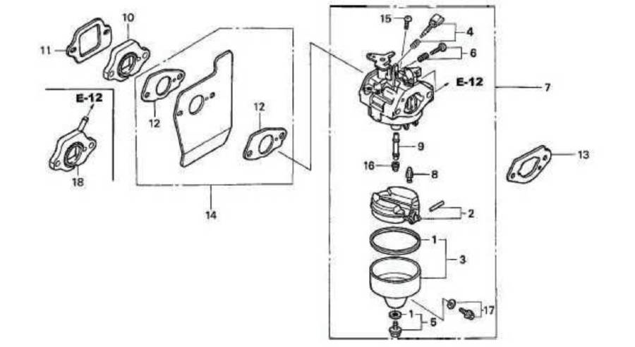
The Honda GCV160 carburetor diagram shows the location, arrangement, and function of the components responsible for mixing fuel with air before combustion. The main components include the carburetor body, float bowl, float, float valve, main jet, main nozzle, choke valve, throttle valve, and gaskets. Understanding how these parts fit together helps identify damaged components, locate fuel restrictions, and reassemble the carburetor correctly after maintenance.
The Honda GCV160 is a 160cc four-stroke engine commonly used in lawn mowers and other outdoor power equipment. Its carburetor uses a float-controlled fuel chamber and calibrated passages to regulate fuel delivery according to engine operating conditions. The choke valve enriches the fuel-air mixture during cold starting, while the throttle valve regulates airflow to support engine speed control.
A Honda GCV160 carburetor exploded-view diagram separates individual components to illustrate their positions and assembly relationships. However, carburetor configurations and replacement part numbers can vary depending on the engine model, type code, and production specifications. Matching the diagram to the engine identification information is essential when ordering replacement parts.
This guide explains how to read the carburetor diagram, identify each major component, understand fuel flow, interpret assembly positions, and recognize common carburetor-related problems.
What Does the Honda GCV160 Carburetor Diagram Show?
The Honda GCV160 carburetor diagram shows the carburetor’s internal components, their positions, and how they connect to form the fuel delivery system. An exploded-view diagram separates individual parts, including the carburetor body, float bowl, float valve, main jet, main nozzle, and gaskets, to illustrate their assembly relationships. Each component is assigned a reference number that corresponds to a parts list, allowing users to identify individual parts before cleaning, repairing, or replacing them.
The Honda GCV160 carburetor is mounted between the air cleaner assembly and the engine’s intake port. Air enters through the air cleaner, passes through the carburetor’s venturi, and carries atomized fuel toward the combustion chamber. The carburetor connects to the fuel supply through a fuel inlet and to the engine’s control system through throttle and choke mechanisms. These connections explain why the diagram includes both internal fuel-metering components and external mounting or control parts.
A Honda GCV160 exploded-view diagram uses numbered callouts and connecting lines to identify components. The callout numbers indicate positions in the accompanying parts catalog rather than installation steps or universal part numbers. For example, the float bowl appears below the carburetor body, while the float and float valve sit inside the fuel chamber. The main jet and main nozzle occupy fuel-metering passages within the carburetor body.
The correct diagram depends on the engine’s complete identification information. Honda GCV160 engines were produced in multiple configurations, and differences in carburetor assemblies, gasket arrangements, and replacement part numbers can affect compatibility. An OEM parts diagram matched to the engine model, type, and applicable serial range provides the most reliable reference.
What Are the Parts of a Honda GCV160 Carburetor?
The Honda GCV160 carburetor contains fuel-metering components, air-control components, and sealing components. Each group performs a specific function: fuel-metering parts regulate gasoline delivery, air-control parts manage airflow, and gaskets prevent unwanted fuel or air leakage. Understanding these three groups helps users identify components in the carburetor diagram and determine which parts require inspection during maintenance.
The following table summarizes the major components found in typical Honda GCV160 carburetor assemblies.
| Carburetor part | Primary function |
|---|---|
| Carburetor body | Houses air and fuel passages |
| Float bowl | Stores fuel for metering |
| Float | Responds to fuel level |
| Float valve | Controls fuel entering the bowl |
| Main jet | Meters fuel through a calibrated opening |
| Main nozzle | Introduces metered fuel into the intake airflow |
| Choke valve | Restricts airflow for cold starting |
| Throttle valve | Controls airflow through the carburetor |
| Bowl gasket | Seals the float chamber |
| Mounting gaskets | Seal carburetor mounting interfaces |
These components operate as a connected system. A restriction in the main jet affects fuel delivery, while a damaged float valve can prevent proper fuel-level control. Similarly, a damaged mounting gasket can introduce unmetered air and disrupt the fuel-air mixture.
What Are the Main Fuel Metering Parts of the Honda GCV160 Carburetor?
The main fuel-metering parts are the float bowl, float, float valve, main jet, and main nozzle. Together, they maintain the fuel supply and regulate how gasoline enters the intake airflow. The float-controlled chamber provides a relatively stable fuel level, while calibrated metering passages determine fuel delivery as airflow changes.
The float bowl is attached beneath the carburetor body and serves as a small fuel reservoir. As gasoline enters the chamber, the float rises with the fuel level and moves the float valve toward its seat. When the fuel level drops, the float lowers and allows additional fuel to enter. This mechanism prevents continuous uncontrolled fuel delivery under normal operating conditions.
The main jet contains a precisely sized opening that restricts fuel flow. Fuel passes through the jet and associated nozzle passages before entering the moving intake air. The pressure difference created by airflow through the venturi draws fuel into the air stream, where it breaks into small droplets. A blocked main jet reduces fuel delivery and can contribute to poor acceleration, surging, or an engine that stops under load.
The main nozzle works with the main jet to deliver fuel into the carburetor throat. Deposits from aged gasoline can obstruct its passages and interfere with fuel distribution. During cleaning, these calibrated openings must remain undamaged because enlarging them changes the intended fuel-metering characteristics.
What Are the Air Control Parts of the Honda GCV160 Carburetor?
The primary air-control parts are the choke valve and throttle valve, which regulate airflow under different engine operating conditions. Both are located within the carburetor’s air passage, but they serve different purposes.
The choke valve is positioned near the air inlet. Closing the choke restricts incoming air and increases fuel enrichment during cold starting. This richer mixture helps a cold engine start when gasoline vaporization is less effective. Once the engine warms up, the choke must open sufficiently to restore normal airflow. A choke that remains closed can cause an excessively rich mixture, rough running, or black exhaust smoke.
The throttle valve is positioned farther along the intake passage toward the engine. It regulates the amount of air-fuel mixture entering the engine and therefore influences engine output. On Honda GCV160 applications, throttle movement is coordinated with the governor system, which responds to changes in engine load. For example, when a lawn mower encounters thicker grass, the governor can open the throttle to help maintain the intended operating speed.
Throttle and choke linkages vary between engine configurations. Their springs, levers, and connection points must be matched to the applicable engine diagram rather than assumed to be identical across all GCV160 models.
What Gaskets and Seals Are Used on the Honda GCV160 Carburetor?
The Honda GCV160 carburetor uses sealing components at the float chamber and mounting interfaces to prevent fuel leakage and unwanted air entry. The exact number, shape, and arrangement of these seals depend on the carburetor and engine configuration.
The float bowl gasket seals the connection between the bowl and carburetor body. Its purpose is to retain gasoline inside the fuel chamber while allowing the float mechanism to operate normally. A hardened, torn, or incorrectly seated gasket can allow fuel to escape around the bowl perimeter. Fuel leakage can also originate from the float valve, so the gasket should not automatically be assumed to be the cause.
Mounting gaskets seal the interfaces between the carburetor, intake components, and air cleaner assembly. These gaskets contain openings that must align with the corresponding air passages, mounting holes, and other functional ports. Incorrect gasket placement can obstruct a passage or allow unmetered air to enter downstream of the carburetor.
Some assemblies also use additional seals around specific components or passages. During disassembly, the original gasket sequence and orientation should be documented before removal. Replacement seals should match the applicable Honda parts diagram, particularly when multiple similar-looking gaskets are included in a repair kit.
How Does the Honda GCV160 Carburetor Work?
The Honda GCV160 carburetor works by combining gasoline with incoming air in a controlled ratio before delivering the mixture to the engine’s combustion chamber. It uses a float-controlled fuel reservoir, calibrated fuel passages, and airflow through a venturi to regulate fuel delivery. The choke and throttle valves adjust airflow according to starting conditions and engine load.
Fuel travels from the fuel tank through the fuel line and enters the carburetor through its fuel inlet. The float valve regulates the amount of gasoline entering the float bowl. As the fuel level rises, the float lifts and moves the valve toward its seat, restricting additional fuel flow. When the engine consumes fuel, the float drops and the valve opens again. This continuous movement maintains the fuel level required for consistent carburetor operation.
Air enters the carburetor through the air cleaner and passes through the venturi, a narrowed section of the intake passage. As air accelerates through the venturi, static pressure decreases, creating a pressure difference that draws gasoline from the float chamber through the fuel-metering system. Fuel passes through the main jet and associated nozzle passages before entering the moving air stream. The resulting mixture travels through the intake port and into the combustion chamber when the intake valve opens.
The choke valve controls mixture enrichment during cold starting. Closing the choke restricts incoming air and increases the pressure difference that draws fuel into the intake stream, producing a richer mixture. This compensates for reduced gasoline vaporization when the engine is cold. Once the engine starts and warms up, the choke opens to restore normal airflow. Depending on the GCV160 configuration, choke operation may be manual or controlled by an automatic mechanism.
The throttle valve regulates the amount of air-fuel mixture entering the engine. Its position is coordinated with the governor system, which adjusts throttle opening as engine load changes. For example, when a lawn mower encounters dense grass, engine speed tends to decrease. The governor responds by opening the throttle farther, increasing mixture delivery to help maintain operating speed. When the load decreases, the governor reduces throttle opening.
The carburetor also uses additional low-speed fuel passages to support operation when the throttle is nearly closed. These passages deliver fuel under conditions where airflow through the main venturi is insufficient for the main metering system to supply the required mixture. Restrictions in these small passages can cause unstable idling, surging, or poor low-speed operation even when the main jet is clear.
How Are Honda GCV160 Carburetor Parts Assembled?
Honda GCV160 carburetor parts are assembled by installing the internal fuel-metering components, securing the float chamber, and reconnecting the carburetor to the engine’s intake and control systems. The correct assembly sequence depends on the specific carburetor configuration, but the main relationships between the float, float valve, main jet, float bowl, and mounting gaskets remain consistent across typical float-type assemblies.
The main jet and associated nozzle components fit into designated fuel passages within the carburetor body. Their calibrated openings must remain clean and unobstructed. During installation, each component must be seated in its correct location without damaging threads or metering surfaces. The main nozzle must also be positioned correctly because its openings determine how fuel enters the intake airflow. Incorrect installation can restrict fuel delivery or interfere with normal mixture formation.
The float and float valve are installed together inside the fuel chamber. The float valve fits into its valve seat, while the float connects to its supporting pivot. As the float moves upward, it closes the valve to restrict incoming gasoline. The float must move freely without binding against the carburetor body. For example, a bent float component or incorrectly positioned valve can prevent the fuel inlet from closing properly, causing excessive fuel accumulation and possible leakage.
The float bowl fits beneath the carburetor body and encloses the fuel reservoir. A sealing gasket sits between the bowl and the carburetor body to prevent gasoline from escaping. The bowl must be positioned according to the original configuration, especially when its shape or drain arrangement requires a specific orientation. Its retaining fastener should be tightened according to the applicable service specifications. Excessive tightening can damage threads, deform sealing surfaces, or compress the gasket unevenly.
Carburetor mounting components must also be installed in the correct sequence. Depending on the engine configuration, these include mounting gaskets, an insulator, and connections to the air cleaner and intake assembly. Each gasket must align with the mounting holes and functional passages. A gasket installed backward or in the wrong position can obstruct airflow or introduce an air leak that disrupts fuel metering.
Throttle and choke linkages are connected after the carburetor is positioned for installation, following the arrangement specified for the engine model. The governor linkage, return springs, and choke connections must move freely without interference. Incorrect spring placement or linkage routing can affect throttle response and governed engine speed. The original connection positions should therefore be recorded before disassembly and verified against the appropriate Honda service documentation during reassembly.
Before returning the engine to service, inspect the assembled carburetor for proper float operation, secure fuel connections, correctly seated gaskets, and unrestricted throttle and choke movement. Reconnect the fuel supply and check for leaks before starting the engine. Any visible gasoline leakage requires correction before operation. Final verification should include stable engine operation and correct response to changing loads, without altering factory-set governor adjustments.
How Do You Find the Correct Honda GCV160 Carburetor Parts Diagram?
To find the correct Honda GCV160 carburetor parts diagram, identify the engine’s complete model designation, type code, and serial number, then match those details to the appropriate Honda OEM parts catalog. The GCV160 engine family includes multiple configurations with differences in carburetor assemblies, control linkages, gaskets, and replacement part numbers. Using the engine family name alone does not guarantee that a diagram matches the installed carburetor.
The engine identification information is typically stamped or marked on the engine housing or crankcase. The model designation identifies the engine family, while the type code distinguishes specific equipment configurations. The serial number helps determine the applicable production range when Honda introduced component revisions. For example, two engines identified as GCV160 may require different carburetor assemblies because their choke mechanisms or equipment-specific configurations differ.
Honda OEM parts catalogs organize components into illustrated assemblies, including the carburetor, air cleaner, fuel system, and control mechanisms. To locate the correct illustration, use the engine identification details in an authorized Honda parts lookup or a reliable OEM parts catalog. Select the matching engine configuration and open its carburetor assembly diagram. The exploded view displays individual components with numbered callouts corresponding to a parts list containing descriptions, part numbers, and applicable quantities.
Diagram reference numbers are not the same as Honda OEM part numbers. A callout identifies a component’s position in a particular illustration, while the associated OEM part number identifies the replacement component. For example, a diagram may separately identify the float set, float valve, main jet, and carburetor assembly. Each item must be matched to the corresponding catalog entry rather than identified solely by its appearance or callout number.
Carburetor part compatibility also depends on production specifications. Honda may use different main jet sizes, carburetor body configurations, or control mechanisms across engine variants. A replacement carburetor that fits the mounting studs may still have different fuel-metering characteristics or linkage connections. Compare the OEM part number, engine type, applicable serial range, and any listed supersession information before selecting a replacement.
When the original carburetor remains installed, its physical characteristics provide an additional identification reference. Compare the fuel inlet position, mounting-hole arrangement, choke mechanism, throttle linkage connections, and float bowl configuration with the catalog illustration. These features help identify obvious mismatches, but they do not replace verification using the engine identification code and OEM parts information.
The most reliable approach is to use the model-specific Honda exploded-view diagram as the primary reference and the installed carburetor as a secondary comparison. This ensures that the selected illustration supports accurate component identification, correct gasket placement, and compatible replacement-part selection during maintenance or repair.
How Do You Clean a Honda GCV160 Carburetor Using the Parts Diagram?
To clean a Honda GCV160 carburetor using the parts diagram, identify the removable fuel-metering components, disassemble the float chamber, clean the fuel passages, and reassemble each part in its correct position. The exploded-view diagram helps locate the float bowl, float valve, main jet, and main nozzle while showing how these components fit together.
Begin by shutting off the engine, allowing it to cool, and disconnecting the spark plug cap to prevent accidental starting. Close the fuel valve if equipped, or use an appropriate method to prevent fuel from flowing when the supply line is disconnected. Work in a well-ventilated area away from ignition sources. Before removing the carburetor, photograph the throttle linkage, choke connections, governor springs, and gasket arrangement. These references help prevent incorrect assembly.
Remove the carburetor according to the engine’s service instructions and place it on a clean work surface. Detach the float bowl and inspect its interior for sediment, varnish, corrosion, or water contamination. Old gasoline can leave deposits that restrict fuel delivery. Remove the float and float valve where the design permits, then inspect the valve tip and seat for wear or debris that could prevent proper fuel-level control.
The main jet and small fuel passages require particular attention because their calibrated openings are vulnerable to blockage. Use a carburetor cleaner compatible with the component materials and follow the product’s safety instructions. Clean accessible passages and confirm they are unobstructed. Avoid using steel wire, drill bits, or other hard tools to enlarge jet openings. Damaging a calibrated passage changes fuel delivery and can cause persistent engine performance problems.
Inspect the float bowl gasket, mounting gaskets, and fuel connections before reassembly. Replace damaged seals with parts specified for the engine configuration. Reinstall the float valve, float, metering components, and float bowl in their correct positions, using the diagram to verify orientation. Reconnect the carburetor, fuel line, and control linkages according to the applicable service instructions.
After reassembly, restore the fuel supply and inspect for leaks before reconnecting the spark plug cap and starting the engine. A properly cleaned carburetor should allow consistent fuel delivery, although continued starting or running problems may indicate faults elsewhere in the fuel, ignition, or engine systems.
Read more: Dana 44 vs Dana 30: Which Axle Is Better?
Which Honda GCV160 Carburetor Parts Cause Common Engine Problems?
The Honda GCV160 carburetor components most directly associated with engine problems include the main jet, low-speed fuel passages, float valve, choke valve, throttle linkage, and sealing gaskets. Restrictions, wear, or incorrect assembly can disrupt fuel delivery, airflow, or fuel-level control. The resulting symptoms include hard starting, unstable idling, engine surging, and gasoline leakage.
The table below connects common symptoms to potential carburetor-related causes.
| Engine problem | Potential faulty component | Mechanical explanation |
|---|---|---|
| Engine won’t start | Main jet, float valve, choke | Insufficient fuel delivery or incorrect cold-start enrichment |
| Rough idling | Low-speed fuel passages | Restricted fuel flow at small throttle openings |
| Engine surging | Low-speed passages, intake gaskets | Inconsistent mixture delivery or unmetered air |
| Engine stalls under load | Main jet, fuel inlet | Restricted fuel supply during increased demand |
| Fuel leaks | Float valve, bowl gasket | Incomplete fuel shutoff or damaged sealing surface |
| Black exhaust smoke | Choke valve, float valve | Excessively rich fuel-air mixture |
Which Carburetor Parts Can Cause Starting, Idling, or Fuel Leak Problems?
Starting problems can result from a blocked main jet, restricted fuel supply, or malfunctioning choke mechanism. The engine requires an appropriate fuel-air mixture for ignition, particularly during cold starting. A blocked fuel passage reduces gasoline delivery, while a choke that fails to close can prevent sufficient enrichment. Conversely, a choke that remains closed after starting can produce an excessively rich mixture. Check fuel availability, choke movement, and accessible fuel passages before assuming that the complete carburetor requires replacement.
Rough idling and surging are commonly associated with restricted low-speed fuel passages or unwanted air entering the intake system. At small throttle openings, the carburetor relies on dedicated passages to deliver fuel. Deposits inside these passages can produce an inconsistent mixture, causing engine speed to fluctuate. A damaged intake gasket can create similar symptoms by allowing air to bypass the intended metering path. On governor-controlled GCV160 engines, changing engine speed also causes the governor to adjust throttle position, making an underlying mixture problem appear as repeated acceleration and deceleration.
Fuel leaks are frequently associated with the float valve, float bowl gasket, or fuel-line connections. The float valve should restrict incoming gasoline when the fuel reaches its intended level. Dirt trapped between the valve and its seat, a worn valve tip, or a float that cannot move freely can allow excessive fuel to enter the chamber. Gasoline may then escape through an overflow route or another opening. A damaged bowl gasket can instead allow fuel to leak directly from the joint between the bowl and carburetor body.
Engine stalling under load can occur when the main jet or fuel inlet cannot supply enough gasoline as demand increases. For example, a lawn mower may operate at light load but lose power when cutting thick grass because the restricted fuel system cannot maintain the required mixture. However, similar symptoms can result from a clogged fuel tank vent, restricted air filter, ignition faults, or other mechanical problems. These possibilities should be checked before replacing carburetor components.
Carburetor troubleshooting should identify the affected system before selecting a replacement part. The parts diagram provides a location reference, while inspection and functional testing determine whether the component is actually defective. Cleaning is appropriate for removable deposits, whereas damaged valve tips, deteriorated gaskets, cracked components, and other physical defects generally require replacement with compatible parts.
How Do You Identify a Compatible Honda GCV160 Replacement Carburetor?
To identify a compatible Honda GCV160 replacement carburetor, match the engine’s model, type code, and serial number with the correct Honda OEM part number. Carburetors designed for the GCV160 engine family can differ in fuel-metering specifications, choke mechanisms, throttle connections, and mounting configurations. A replacement must match the engine’s operating requirements rather than simply fit its mounting studs.
Start by locating the engine identification markings on the engine housing or crankcase. Record the complete model designation, type code, and serial number before searching for replacement parts. Use these details to locate the corresponding carburetor assembly in a Honda OEM parts catalog. The catalog identifies the original part number and may list updated or superseding replacements for specific production ranges.
The OEM part number is the primary reference for verifying replacement compatibility. Honda carburetor part numbers commonly use a structured format consisting of multiple groups of letters and numbers. A difference in these identifiers can indicate a different assembly specification, although an officially documented supersession may establish compatibility between two numbers. Verify replacement information against the applicable parts catalog instead of assuming that similar-looking carburetors are interchangeable.
Physical compatibility requires checking the carburetor’s mounting-hole spacing, intake opening, fuel inlet position, choke mechanism, and throttle linkage connections. For example, a replacement with matching mounting dimensions but a different choke linkage may not operate correctly with the engine’s existing controls. Similarly, differences in main jet calibration can affect fuel delivery even when the carburetor fits the engine mechanically.
Honda OEM carburetors and aftermarket replacements should be evaluated using the same compatibility criteria. Genuine Honda components provide a manufacturer-specified reference for the applicable engine configuration, while aftermarket carburetors require verification of their cross-referenced OEM numbers and mechanical specifications. Product listings that describe a carburetor only as fitting “Honda GCV160” do not establish compatibility with every engine variant.
Before installation, compare the replacement carburetor with the original assembly and the model-specific exploded-view diagram. Confirm that the fuel connections, mounting surfaces, gaskets, and control mechanisms correspond to the required configuration. Install the carburetor according to the applicable service instructions, check for fuel leaks, and verify normal throttle and choke operation before returning the equipment to service.
A correctly matched replacement carburetor restores the intended fuel-metering configuration without requiring modifications to the engine’s original mounting or control systems. If the replacement requires drilling, bending linkage components, or altering the governor mechanism to fit, its compatibility should be reconsidered.