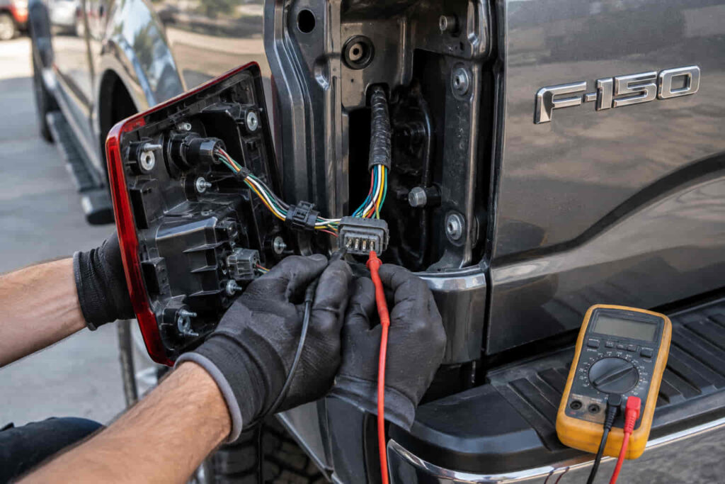
A Ford F150 tail light wiring diagram helps identify how the rear lighting system connects the tail lamps, brake lights, turn signals, reverse lights, ground circuits, connectors, fuses, and vehicle control modules. Because Ford F-150 electrical systems have changed across generations, a wiring diagram should always be matched to the exact model year, body configuration, tail light design, and equipment level.
Understanding the wiring is especially useful when a tail light stops working, an aftermarket light is being installed, a trailer lighting circuit is being diagnosed, or a wiring harness has been damaged. The visible lamp is only one part of the system. Power, ground, signal control, connectors, wiring harnesses, fuses, and electronic modules can all affect whether the tail light operates correctly.
What Is a Ford F150 Tail Light Wiring Diagram?
A Ford F150 tail light wiring diagram is a representation of the electrical connections used by the rear lighting system. It shows how electrical power and control signals travel between the vehicle’s electrical system, wiring harness, connectors, and rear lighting assemblies.
Depending on the F-150 generation, the diagram can include separate circuits for parking or tail lamps, brake lamps, turn signals, reverse lamps, side markers, and ground. Some configurations can also involve electronic body control modules rather than relying on a simple switch-to-bulb circuit.
The purpose of the diagram is not simply to identify which wire reaches the tail light. It provides a map of the electrical relationships needed to diagnose a circuit correctly.
Ford F150 Tail Light Wiring by Model Year
The most important consideration when using a Ford F150 tail light wiring diagram is model year. Ford has redesigned the F-150 several times, and the rear lighting architecture can change between generations.
A wiring diagram for an older F-150 should not automatically be used on a newer truck. Even when two trucks have similar-looking tail light assemblies, their connectors, wire functions, control strategy, and communication with vehicle modules may be different.
Body configuration and equipment can also matter. Differences in standard tail lamps, LED assemblies, trim packages, factory options, and other rear electrical equipment can affect the applicable wiring information.
For this reason, the model year and exact vehicle configuration should be identified before interpreting wire colors or connector positions.
Main Circuits in a Ford F150 Tail Light System
The rear lighting system normally combines several functions within the tail light assembly. Tail or parking lights provide rear illumination when the vehicle lighting system is switched on, while the brake circuit produces a brighter signal when the brake pedal is applied.
Turn signal operation uses the rear lamp to communicate a left or right turn. Depending on the electrical architecture, the brake and turn functions may share portions of the same circuit or may be controlled separately.
Reverse lights operate through their own circuit and are activated when the vehicle is placed in reverse. The exact wiring arrangement depends on the F-150 generation and lighting configuration.
A ground connection is equally important because the lamp needs a complete electrical path for current to return to the vehicle electrical system. A damaged or high-resistance ground can create symptoms that appear to be caused by the lamp itself.
How to Read a Ford F150 Tail Light Wiring Diagram
Reading the diagram starts with identifying the tail light connector and the relevant circuit. The diagram should then be followed from the power source or control module through the harness and connector to the lighting assembly and ground.
Wire colors can provide useful clues, but color alone should not be treated as proof of circuit function. Ford wiring colors and connector arrangements can vary between model years and circuits.
Connector pin numbers are often more useful when diagnosing a specific vehicle because they identify the physical position of a terminal within the connector. The connector view should be interpreted from the correct orientation shown in the service documentation.
A wiring diagram may also contain circuit identifiers, splice points, grounds, fuses, relays, connectors, and module references. These details help determine whether a problem is located at the lamp, harness, connector, power supply, ground, or control side of the circuit.
Ford F150 Tail Light Wire Color and Function
One of the most common searches associated with F-150 tail light wiring is the relationship between wire color and function. However, there is no universal wire-color chart that should be applied to every F-150.
Wire colors can differ by model year, body configuration, lighting system, and connector. Even when a color appears familiar, the correct circuit should be verified using the wiring diagram for the exact vehicle.
This is particularly important when installing aftermarket tail lights or repairing a damaged harness. Connecting a wire based solely on color can result in incorrect brake, turn signal, parking light, or ground connections.
The safest approach is to identify the circuit by its diagram designation, connector location, electrical testing, and vehicle-specific service information.
Ford F150 Tail Light Connector Wiring
The tail light connector provides the physical interface between the vehicle wiring harness and the lamp assembly. A connector may contain multiple terminals because several lighting functions can share the same assembly.
When diagnosing a connector, inspection should begin with physical condition. Corrosion, water intrusion, damaged terminals, loose connections, broken locking tabs, or pushed-back pins can interrupt the circuit even when the wiring appears intact.
Connector pin identification is especially important when a replacement tail light or harness is being installed. The replacement component must match the electrical architecture of the specific F-150 rather than only matching the physical shape of the lamp.
Read more: Ford F150 Spark Plug Torque Specs
Ford F150 Tail Light Ground Circuit
A tail light cannot operate correctly without a reliable electrical ground. Ground problems can create intermittent operation, dim lighting, incorrect lamp behavior, or multiple lighting functions appearing to fail at the same time.
When several functions in the same lamp assembly behave abnormally, the ground and connector should be considered along with the individual lamp circuit.
Ground testing should be performed according to the applicable diagnostic procedure. Simply seeing that a ground wire is physically connected does not prove that the circuit has low resistance under operating conditions.
Why Is My Ford F150 Tail Light Not Working?
A non-functioning tail light can result from several different faults. The lamp assembly itself may be defective, but the problem can also occur in the fuse, connector, wiring harness, ground circuit, switch input, or electronic control system.
The first diagnostic step is to determine exactly which lighting function has failed. A parking light failure is not necessarily the same circuit problem as a brake light failure or reverse light failure.
If only one side is affected, the investigation can focus more closely on that lamp, its connector, wiring, and ground. If both sides fail simultaneously, a shared power supply, control input, fuse, module output, or common circuit becomes more relevant.
This functional distinction makes the wiring diagram much more useful than simply replacing the bulb or lamp assembly without testing.
Ford F150 Tail Light Fuse and Power Supply
Fuses protect electrical circuits from excessive current. A blown fuse can interrupt a tail light circuit, but replacing the fuse without determining why it failed can leave an underlying electrical problem unresolved.
The exact fuse location and circuit designation depend on the F-150 model year and electrical configuration. The correct fuse should therefore be identified from the vehicle-specific fuse and wiring information.
If a replacement fuse fails again, the circuit should be investigated for a short circuit, damaged wiring, incorrect installation, or another electrical fault rather than repeatedly replacing the fuse.
Ford F150 Tail Light Wiring and BCM Control
Modern F-150 lighting systems can use electronic body control modules to manage lighting functions. This means the tail light may not be controlled by a simple mechanical switch and direct power path.
A module can receive an input from a vehicle control or switch, process the request, and control the corresponding lighting circuit. Depending on the generation, diagnostic communication and electronic monitoring can also be part of the system.
This is why testing voltage at the lamp alone may not always identify the root cause. The correct diagnostic path may require checking inputs, outputs, circuit continuity, grounds, connector integrity, and module-related faults.
How to Test Ford F150 Tail Light Wiring
Electrical testing should begin with the specific function that is not operating. The test should then follow the circuit shown in the correct wiring diagram.
A multimeter or suitable electrical test equipment can be used to determine whether the required electrical conditions are present at the relevant connector terminals. Voltage testing should be combined with ground and continuity checks when appropriate.
A circuit that shows voltage with no load does not necessarily prove that it can supply the required current under operating conditions. High resistance caused by corrosion or damaged wiring can produce misleading results.
The objective is to locate the point where the expected electrical condition disappears. Once that point is identified, the wiring diagram can be used to determine which component, connector, splice, or section of harness lies between the known-good and failed portions of the circuit.
Ford F150 Tail Light Wiring for LED Upgrades
Replacing factory tail lights with LED assemblies can change the electrical characteristics of the lighting circuit. Compatibility depends on the design of the replacement lamp and the electrical architecture of the truck.
An aftermarket LED tail light may require a compatible connector, resistor, adapter, module, or other integration component depending on the application. The correct solution varies by F-150 generation and the specific replacement light.
An installation that physically fits the truck is not necessarily electrically compatible. The brake, turn, parking, and reverse functions should all be verified after installation, along with warning messages or abnormal lamp behavior.
Ford F150 Tail Light Wiring for Trailer Connections
The trailer lighting system should not automatically be treated as an extension of the tail light wires. Factory trailer systems can use dedicated circuits and control strategies designed to support trailer lighting.
When diagnosing a trailer lighting problem, it is important to determine whether the fault exists in the truck’s rear lighting, the trailer connector, the trailer wiring harness, or the trailer itself.
A vehicle-specific wiring diagram can help separate the truck-side lighting circuit from the trailer-side circuit and prevent unnecessary modifications to the factory tail light wiring.
What Causes Ford F150 Tail Light Wiring Problems?
Tail light wiring problems can develop from corrosion, water intrusion, physical damage, connector deterioration, loose terminals, harness chafing, previous modifications, or incorrect aftermarket installations.
The rear of a pickup is exposed to road spray, moisture, dirt, cargo movement, and physical impacts. Harnesses routed near the bed, frame, bumper, and tailgate can therefore be exposed to conditions that eventually affect electrical reliability.
Intermittent problems deserve particular attention because movement, vibration, moisture, and temperature can change the electrical connection temporarily. A wiring diagram combined with targeted testing is usually more effective than repeatedly replacing components.
How to Repair Ford F150 Tail Light Wiring
The appropriate repair depends on the location and type of failure. A damaged connector may require connector repair or replacement, while a broken wire may require a properly engineered harness repair.
A wiring repair should preserve the electrical and mechanical integrity of the original circuit. The repaired section should be protected against moisture, vibration, abrasion, and future mechanical damage.
Before completing the repair, the affected lighting functions should be tested individually. Brake, turn, parking, and reverse functions should all operate correctly when applicable to the vehicle configuration.
Ford F150 Tail Light Wiring Diagram for Troubleshooting
The most effective use of a Ford F150 tail light wiring diagram is to turn a symptom into a defined electrical path. Instead of assuming that a failed tail light means the bulb or lamp is defective, the diagram allows the technician to trace the circuit from its source through the relevant controls, connectors, wiring, lamp assembly, and ground.
The exact diagnostic path should always follow the vehicle-specific diagram. This becomes increasingly important on newer F-150 models where electronic modules and monitored circuits can be involved.
A correct diagram therefore provides more than wire colors. It establishes the relationship between the components that make the lighting system operate.
FAQ About Ford F150 Tail Light Wiring Diagram
Is there one Ford F150 tail light wiring diagram for all years?
No. F-150 tail light wiring can vary by model year, generation, body configuration, trim, lighting equipment, and electrical architecture. The diagram should be matched to the exact vehicle.
What are the main Ford F150 tail light wires?
The rear lighting system can include circuits for tail or parking lights, brake lights, turn signals, reverse lights, and ground. Exact wire functions and colors depend on the vehicle configuration.
Can I identify F150 tail light wires by color?
Wire color can help identify a circuit, but it should not be used as the only source of verification. The vehicle-specific wiring diagram and connector pin information provide a more reliable reference.
Why does one Ford F150 tail light not work?
Possible causes include a failed lamp, damaged wiring, poor ground, corroded connector, blown fuse, or an electrical control problem. The exact cause should be determined by testing the affected circuit.
Why are both F150 tail lights not working?
When both sides fail, a shared power supply, fuse, control circuit, module output, or common ground becomes more relevant. The correct wiring diagram can identify which components are shared by the two sides.
Can I use an aftermarket LED tail light on my F150?
An aftermarket LED tail light can be compatible with an F-150 when it is designed for the specific vehicle configuration. Physical fitment alone does not guarantee electrical compatibility, so all lighting functions should be verified after installation.