A Briggs and Stratton carburetor diagram shows the location, arrangement, and connections of components that control the air-fuel mixture in a small gasoline engine. The diagram identifies essential parts such as the float bowl, main jet, fuel inlet, choke plate, throttle plate, and governor linkage. Each component performs a specific function in delivering the correct fuel mixture for engine starting, acceleration, and steady operation.
Briggs & Stratton uses different carburetor designs across its lawn mower engines, generators, pressure washers, and other outdoor power equipment. Float-type carburetors contain a fuel bowl, float, and inlet needle, while diaphragm-type carburetors use a different fuel-metering arrangement. Consequently, the correct parts diagram depends on the engine model, type, and carburetor configuration.
Understanding a Briggs and Stratton carb diagram helps identify individual components, trace fuel passages, inspect linkage connections, and locate parts associated with starting problems, fuel leaks, or uneven engine operation. An exploded diagram also shows how components fit together, making it useful during carburetor cleaning, inspection, and reassembly.
This guide explains the main carburetor parts, their functions, fuel-flow operation, and linkage connections. It also covers how to identify the correct diagram for a specific Briggs & Stratton engine and use it to support basic troubleshooting and maintenance.
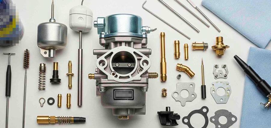
What Does a Briggs and Stratton Carburetor Diagram Show?
A Briggs and Stratton carburetor diagram shows the internal components, assembly positions, and mechanical connections of the carburetor used in a Briggs & Stratton small engine. The diagram identifies fuel-metering parts, air-control components, mounting hardware, and linkage connections. It serves as a visual reference for locating components, understanding their arrangement, and identifying replacement parts during maintenance or repair.
There are three main types of Briggs & Stratton carburetor diagrams: exploded parts diagrams, labeled component diagrams, and linkage diagrams. Each provides different technical information. An exploded parts diagram separates individual components to illustrate their assembly order, including the carburetor body, gaskets, jets, seals, and mounting hardware. A labeled component diagram identifies the position and function of parts within the carburetor. A linkage diagram shows how the throttle lever, governor spring, and choke mechanism connect to the engine’s control system.
A typical float-type Briggs & Stratton carburetor diagram includes the fuel inlet, float bowl, float, inlet needle, main jet, venturi, choke plate, and throttle plate. The fuel inlet directs gasoline into the carburetor, while the float and inlet needle regulate fuel entering the bowl. The main jet meters fuel into the airflow passing through the venturi. The choke plate restricts incoming air during cold starting, and the throttle plate controls airflow into the engine. Diaphragm-type carburetors use a different fuel-metering arrangement and do not necessarily contain these float-system components.
Carburetor diagrams also use reference numbers to connect illustrated components with an accompanying parts list. These numbers identify specific parts and help users locate the corresponding manufacturer part numbers. However, Briggs & Stratton carburetor diagrams are not interchangeable across all engine models. Differences in fuel systems, choke mechanisms, mounting configurations, and linkage arrangements require users to verify the engine model and type before selecting a diagram. The correct illustrated parts list provides the most reliable reference for identifying components and confirming replacement-part compatibility.
What Are the Main Parts of a Briggs and Stratton Carburetor?
A Briggs & Stratton carburetor consists of fuel-metering components, airflow controls, and sealing parts that regulate the air-fuel mixture entering a gasoline engine. The main components in a typical float-type carburetor include the carburetor body, float bowl, float, inlet needle, main jet, venturi, choke plate, throttle plate, and gaskets. Each component has a specific function in controlling fuel delivery, engine starting, and operating speed.
The carburetor body houses the internal fuel passages and provides mounting points for the air filter assembly, engine intake, and control linkages. Gaskets and seals prevent fuel leakage and unwanted air entry at connection points. The exact arrangement depends on the engine series and carburetor design. For example, Briggs & Stratton diaphragm-type carburetors use a flexible diaphragm to regulate fuel delivery instead of the float-and-bowl system found in many other models.
What Do the Float Bowl and Needle Valve Do?
The float bowl stores a small supply of gasoline, while the float and inlet needle regulate the fuel level inside the carburetor. These components work together to maintain a relatively consistent fuel level for the main metering circuit during engine operation.
As gasoline enters the carburetor through the fuel inlet, the float rises with the fuel level. When the fuel reaches its designed height, the float pushes the inlet needle against its seat, restricting additional fuel flow. As the engine consumes gasoline, the fuel level drops, allowing the needle to open and admit more fuel. This mechanical regulation prevents the bowl from continuously filling while maintaining an available fuel supply.
A damaged float, worn inlet needle, or contaminated needle seat can interfere with fuel regulation. For example, debris trapped between the needle and its seat can prevent complete closure, allowing excess gasoline to enter the bowl and potentially leak through the carburetor. A Briggs and Stratton carburetor parts diagram identifies the position of these components and their relationship to the fuel inlet and carburetor body.
What Is the Function of the Main Jet and Venturi?
The main jet meters gasoline into the carburetor’s fuel-delivery circuit, while the venturi creates the pressure difference needed to draw fuel into the incoming airflow. Together, these components help produce the air-fuel mixture required for combustion.
The venturi is a narrowed section of the carburetor’s air passage. As air moves through this restriction, its velocity increases and static pressure decreases. The resulting pressure difference draws gasoline from the fuel supply through the metering passages. The main jet restricts fuel flow through a calibrated opening, helping control the amount of gasoline delivered under the operating conditions served by that circuit. Some carburetors also contain an emulsion tube that introduces air into the fuel before it enters the main airflow.
A restricted main jet reduces fuel delivery and can cause lean-running symptoms, including engine surging, hesitation, or loss of power. For example, gasoline residue left after prolonged storage can obstruct the jet’s small opening and interfere with normal fuel flow. A carburetor diagram helps identify the main jet and related passages for inspection. However, jet location and accessibility differ between Briggs & Stratton carburetor models.
How Do the Choke Plate and Throttle Plate Work?
The choke plate controls incoming air during engine starting, while the throttle plate regulates airflow to control engine power and speed. Both components are positioned in the carburetor’s air passage, but they perform different functions.
The choke plate is generally located near the carburetor’s air inlet. Closing the choke restricts incoming air and increases the fuel-richness of the mixture delivered during cold starting. This helps compensate for reduced gasoline vaporization when the engine is cold. Once the engine starts and warms sufficiently, the choke opens to restore normal airflow. Briggs & Stratton engines may use manual choke controls, automatic choke mechanisms, or primer-based starting systems, depending on the model.
The throttle plate is positioned closer to the engine intake and regulates how much air-fuel mixture enters the combustion chamber. Opening the throttle increases airflow and allows the engine to produce more power when sufficient fuel is supplied. Closing the throttle restricts airflow and reduces engine output. On many Briggs & Stratton lawn mower engines, the governor mechanism adjusts the throttle plate automatically to maintain the intended engine speed as the mechanical load changes.
For example, when a lawn mower encounters thicker grass, the increased cutting load tends to reduce engine speed. The governor responds by opening the throttle further, allowing the engine to develop additional power. A Briggs and Stratton carburetor diagram identifies the throttle shaft, choke shaft, and external linkage connection points, helping distinguish the two control mechanisms during inspection and reassembly.
How Does a Briggs and Stratton Carburetor Work?
A Briggs & Stratton carburetor works by mixing gasoline with incoming air and regulating the mixture delivered to the engine’s combustion chamber. It uses airflow through a narrowed passage called the venturi to create a pressure difference that draws fuel into the intake air. The carburetor adjusts fuel delivery according to airflow, throttle position, and the design of its metering circuits.
The process begins when gasoline enters the carburetor through the fuel inlet. In a float-type carburetor, fuel collects in the float bowl, where the float and inlet needle maintain the designed fuel level. As the engine draws air through the carburetor, the air passes through the venturi, increasing in velocity and decreasing in static pressure. This pressure difference draws gasoline through the main jet and associated fuel passages into the airstream. The fuel breaks into small droplets and mixes with the incoming air before traveling through the intake passage toward the combustion chamber.
Fuel delivery changes according to engine operating conditions. During cold starting, the choke plate restricts incoming air to provide a richer mixture that supports ignition when gasoline vaporizes less readily. Once the engine starts and warms up, the choke opens to allow normal airflow. At higher engine loads, the throttle plate opens further, increasing airflow and allowing the carburetor’s metering system to supply the fuel required for additional power. Some Briggs & Stratton carburetors also include idle or transition circuits that supply fuel when airflow through the main venturi is insufficient for normal main-circuit operation.
For example, when a lawn mower moves from short grass into thick grass, the cutting load increases and engine speed initially tends to decrease. The governor responds by adjusting the throttle linkage, opening the throttle plate to increase the available air-fuel mixture. As combustion produces additional torque, the engine can recover toward its governed operating speed. This process continues as the load changes, allowing the engine to maintain relatively stable performance without constant manual throttle adjustments.
The operating principle depends on the carburetor design. Float-type carburetors regulate fuel supply through a float bowl and inlet needle, while diaphragm-type designs use a flexible diaphragm and associated fuel passages to control fuel delivery. Although both designs use airflow and pressure differences to meter gasoline, their internal components and fuel-routing arrangements differ. Identifying the correct Briggs and Stratton carburetor diagram is therefore essential for understanding the specific fuel system installed on an engine.
How Do You Read a Briggs and Stratton Carburetor Linkage Diagram?
A Briggs and Stratton carburetor linkage diagram shows how the throttle linkage, governor spring, governor arm, and choke linkage connect to control engine speed and airflow. Each connection transfers mechanical movement between the engine’s governor system, carburetor levers, and operator controls. Reading the diagram correctly helps identify linkage positions, understand spring functions, and prevent incorrect assembly after carburetor removal or maintenance.
The throttle linkage connects the governor arm to the carburetor’s throttle lever. As engine load changes, the governor mechanism moves the linkage to adjust the throttle plate opening. When engine speed decreases under increased load, the governor allows the throttle to open further, increasing the air-fuel mixture entering the engine. As engine speed rises, the governor moves the throttle toward a more closed position. This continuous adjustment helps maintain the engine’s governed operating speed.
The governor spring provides the opposing force that establishes the governor’s speed-control balance. On mechanically governed Briggs & Stratton engines, spring tension acts against the force generated by the governor mechanism. Changes in engine speed alter this balance, causing the governor arm and throttle linkage to move. For example, when a lawn mower encounters heavy grass, the governor responds to the reduction in engine speed by allowing additional throttle opening. The spring’s attachment points and tension characteristics depend on the specific engine model, making the correct linkage diagram essential for identifying its original configuration.
The choke linkage operates separately from the governor-controlled throttle linkage on engines equipped with a choke plate. It connects the choke control mechanism to the choke shaft, allowing the plate to open or close during starting and warm-up. Manual choke systems use a control lever or cable, while automatic choke systems use temperature-sensitive mechanisms or other engine-specific controls. Some Briggs & Stratton engines use primer systems instead of conventional choke linkages, so the diagram must match the installed starting system.
To read a carburetor linkage diagram, first identify the throttle shaft lever, governor arm, spring attachment points, and choke lever where applicable. Next, trace each linkage rod between its illustrated connection points and distinguish rigid rods from tension springs. An exploded parts diagram identifies individual components, while a dedicated linkage illustration or service manual provides more useful information about their installed positions and routing. Compare these references with the actual engine before disconnecting any components.
Incorrect linkage installation can affect engine speed regulation and safe operation. A spring attached to the wrong hole, a bent linkage rod, or a binding throttle lever can prevent the governor from controlling engine speed as designed. For example, excessive governor spring tension or an incorrectly assembled throttle linkage may contribute to engine overspeed, while restricted linkage movement can cause unstable operation or insufficient power. Never alter governor spring attachment points or adjustments to increase engine speed beyond the manufacturer’s specifications. Use the model-specific Briggs & Stratton service instructions to verify linkage routing and governor settings before operating the engine.
How Do You Find the Correct Briggs and Stratton Carburetor Diagram for Your Engine?
To find the correct Briggs and Stratton carburetor diagram, identify the engine’s model, type, and code numbers, then use the manufacturer’s illustrated parts documentation to locate the matching carburetor assembly. These identification numbers help distinguish engines with different fuel systems, carburetor configurations, and linkage arrangements. Matching the diagram to the engine prevents confusion between visually similar carburetors that use different internal components or replacement parts.
Briggs & Stratton produces multiple small-engine families with different carburetor designs. For example, some engines use float-type carburetors with removable fuel bowls, while others use diaphragm-type carburetors connected directly to the fuel tank. Carburetor mounting patterns, choke mechanisms, fuel passages, and governor linkages also vary between engine configurations. Consequently, identifying a carburetor by appearance alone does not guarantee that its diagram or replacement components will match the installed engine.
Where Is the Briggs and Stratton Engine Model Number Located?
The Briggs & Stratton engine model number is typically stamped or marked on the engine housing, blower housing, valve cover, or another manufacturer-designated identification area. Its exact location depends on the engine series and construction. The identification marking generally contains three pieces of information: the model number, type number, and code number.
The model number identifies the engine’s basic design and configuration. The type number distinguishes specific equipment configurations and component variations within that model. The code number provides manufacturing identification information, including production dating. Together, these numbers help determine which illustrated parts list and service documentation apply to the engine.
For example, two Briggs & Stratton engines belonging to the same model family may use different carburetor assemblies because of variations in their fuel systems, control linkages, or equipment applications. Checking the complete engine identification prevents selecting parts based only on engine horsepower or external appearance. If the identification marking is difficult to read, inspect the designated stamping areas carefully and consult the manufacturer’s engine identification guidance rather than estimating missing characters.
Where Can You Find Official Briggs and Stratton Carburetor Diagrams?
Official Briggs & Stratton carburetor diagrams are available through the manufacturer’s parts lookup resources, illustrated parts lists, and engine-specific service documentation. These resources identify carburetor assemblies and associated components using reference numbers that correspond to manufacturer part numbers.
The official Briggs & Stratton website provides access to product support and parts information. To locate the appropriate diagram, enter the engine identification details into the relevant parts lookup system and select the documentation matching the engine configuration. Locate the carburetor or fuel-system section within the illustrated parts list, then compare the displayed assembly with the carburetor installed on the engine.
An illustrated parts diagram typically uses numbered callouts to identify components such as the carburetor assembly, gaskets, fuel bowl, mounting hardware, and other serviceable parts. The accompanying parts list connects each callout to its description and part number. Some internal carburetor components are available individually, while others are supplied only as part of a repair kit or complete assembly. Parts availability depends on the carburetor design and manufacturer service specifications.
Before ordering replacement components, verify the engine model and type, compare the carburetor configuration, and confirm the applicable part number. If the engine has previously received a replacement carburetor, the installed component may differ from its original factory configuration. In that situation, checking the carburetor’s identification markings and physical connections helps establish whether the existing assembly matches the manufacturer’s documented specifications.
The correct carburetor diagram must match the engine configuration, not simply the Briggs & Stratton brand name. Using the appropriate illustrated parts list ensures that component identification, linkage references, and replacement-part selection are based on the actual engine rather than a generic carburetor illustration.
What Carburetor Problems Can You Identify Using a Briggs and Stratton Diagram?
A Briggs and Stratton carburetor diagram helps identify components associated with three common engine problems: fuel leaking, hard starting, and engine surging. By showing the locations of fuel passages, metering components, gaskets, and throttle connections, the diagram provides a reference for inspecting parts that may contribute to these symptoms. However, a diagram identifies potential problem areas rather than confirming the cause of an engine malfunction.
Fuel leaking is commonly associated with problems involving the float, inlet needle, needle seat, fuel bowl gasket, or fuel connections. In a float-type carburetor, the inlet needle must seal against its seat when gasoline reaches the specified level. A worn needle tip, damaged float, or debris trapped in the needle seat can prevent proper closure, allowing excess fuel to enter the bowl. Damaged bowl gaskets and loose fuel-line connections can also cause external leaks. The carburetor diagram identifies these components and their sealing locations, helping determine where inspection should begin. Diaphragm-type carburetors require different inspection points because they do not use the same float-bowl arrangement.
Hard starting can result from restricted fuel passages, a malfunctioning choke, contaminated gasoline, or insufficient fuel delivery. The main jet and associated metering passages control fuel flow, while the choke mechanism helps provide the richer mixture required during cold starting. For example, a blocked fuel passage can prevent adequate gasoline delivery even when the fuel tank contains sufficient fuel. A choke plate that fails to close properly can also make cold starting difficult. Using the carburetor diagram, owners can locate these components and check their condition. Ignition faults, compression problems, and stale fuel must also be considered because hard starting is not always caused by the carburetor.
Engine surging occurs when engine speed repeatedly increases and decreases instead of remaining stable under a consistent load. Carburetor-related causes include restricted jets, inconsistent fuel delivery, and unwanted air entering through damaged intake gaskets. A partially obstructed main jet can produce a lean mixture, causing engine speed to drop and prompting the governor to open the throttle. As operating conditions change, this interaction can produce repeated speed fluctuations. A Briggs and Stratton carburetor diagram helps locate the main jet, fuel passages, and gasket connections, while a linkage diagram identifies the governor and throttle components involved in speed regulation.
Accurate carburetor troubleshooting requires matching the observed symptom with physical inspection and the correct engine diagram. Fuel leaks require attention to sealing and fuel-level components, hard starting requires checking fuel delivery and starting controls, and surging requires evaluating fuel metering alongside governor operation. Stop operating an engine with an active gasoline leak, and disconnect the spark plug wire before carburetor inspection to prevent accidental starting. Identifying the affected components before disassembly reduces unnecessary part replacement and helps preserve the original carburetor configuration.
Read more: Honda GCV160 Carb Diagram: Parts & Functions
How Do You Use a Briggs and Stratton Carburetor Diagram for Cleaning?
To clean a Briggs & Stratton carburetor using a diagram, identify the removable components, locate the fuel passages, inspect the jets and gaskets, and follow the illustrated assembly arrangement during reinstallation. The diagram provides a reference for component positions and helps prevent incorrect assembly. Cleaning procedures depend on whether the engine uses a float-type or diaphragm-type carburetor, so the diagram must match the engine model before disassembly begins.
Start by turning off the engine, allowing it to cool, and disconnecting the spark plug wire to prevent accidental starting. Shut off the fuel supply if the engine has a fuel valve, or secure the fuel line using a manufacturer-approved method. Work in a well-ventilated area away from flames, sparks, and other ignition sources. Before removing the carburetor, photograph the throttle linkage, governor spring, choke connections, and fuel-line routing. These photographs supplement the diagram by recording the original installation positions.
For a float-type carburetor, the diagram identifies the float bowl, bowl gasket, float, inlet needle, main jet, and associated fuel passages. Remove only the components specified as serviceable in the applicable manufacturer instructions. Inspect the float bowl for sediment, corrosion, and fuel residue. Check the main jet and accessible fuel passages for deposits that restrict gasoline flow. Use a carburetor cleaner compatible with the component materials, following the product instructions. Avoid forcing metal wires or drill bits through calibrated jet openings because enlarging these passages changes fuel-metering characteristics.
Diaphragm-type carburetors require a different cleaning approach. Their diagrams identify the diaphragm, gaskets, fuel passages, and associated metering components instead of a conventional float bowl. Inspect the diaphragm for stiffness, tears, or deformation that could interfere with fuel delivery. Remove rubber diaphragms and other cleaner-sensitive components before applying solvents when required by the service instructions. A damaged diaphragm generally requires replacement rather than cleaning because its flexibility and sealing properties are essential for proper operation.
After cleaning, use the Briggs and Stratton carburetor assembly diagram to verify component placement, gasket orientation, and the correct order of reassembly. Replace damaged seals and gaskets rather than reinstalling components that no longer provide a reliable seal. Reconnect the throttle and choke linkages according to the engine-specific reference, ensuring that the controls move freely without binding. Tighten mounting fasteners to the manufacturer’s specified torque rather than estimating the required force.
A carburetor diagram supports accurate cleaning and reassembly, but it does not replace the manufacturer’s service procedures. Before restarting the engine, inspect fuel connections for leaks, confirm that the throttle and governor linkages are correctly installed, and verify that all removed components have been secured. For example, an incorrectly positioned bowl gasket can allow gasoline to escape, while a misconnected governor spring can interfere with engine speed regulation. Correct component placement helps restore normal fuel delivery and reduces the risk of problems after maintenance.
When Should You Replace Briggs and Stratton Carburetor Parts?
Briggs & Stratton carburetor parts should be replaced when physical damage, excessive wear, corrosion, or failed sealing prevents the components from functioning correctly. Common replacement parts include float bowl gaskets, inlet needles, floats, diaphragms, and fuel seals. Cleaning removes deposits and fuel residue, but it cannot restore damaged sealing surfaces, cracked components, or worn mechanical parts. The correct Briggs and Stratton carburetor diagram helps identify these components and determine whether individual replacements are available for the specific engine model.
A damaged float bowl gasket should be replaced when it becomes cracked, compressed, swollen, or unable to maintain a reliable seal. Similarly, an inlet needle with a worn sealing tip may allow gasoline to continue entering the float bowl after the correct fuel level has been reached. A leaking or fuel-saturated float can also interfere with fuel-level regulation. These defects may cause fuel overflow, unstable engine operation, or difficulty starting. Replacing the affected component restores its intended mechanical function, provided the surrounding parts remain in serviceable condition.
Diaphragm-type carburetors require inspection of different components. A diaphragm that has hardened, stretched, or developed tears may no longer respond correctly to pressure changes, disrupting fuel delivery. Damaged diaphragms and gaskets should be replaced with parts specified for the carburetor model. Main jets and fuel passages, however, do not automatically require replacement when blocked. Deposits can often be removed through proper cleaning, provided the calibrated openings and surrounding surfaces remain undamaged.
When Is Replacing the Entire Carburetor Necessary?
Replacing the entire Briggs & Stratton carburetor is appropriate when its body or essential internal components are damaged beyond practical repair, or when individual replacement parts are unavailable. Severe corrosion, cracked castings, damaged fuel passages, and worn throttle-shaft bores can make rebuilding unreliable. These defects may prevent correct fuel metering or allow unwanted air and gasoline leakage even after cleaning and gasket replacement.
For example, a carburetor with a clogged main jet may only require cleaning, while one with extensive corrosion inside its fuel passages may need complete replacement. A damaged float bowl gasket can be replaced individually when the correct part is available, but a cracked carburetor body generally requires replacing the affected assembly. The decision should consider the extent of damage, replacement-part availability, and the cost of repair compared with a compatible complete carburetor.
Before purchasing a replacement, verify the engine model and type numbers and identify the correct carburetor part number using the Briggs & Stratton illustrated parts list. Compare the replacement’s mounting configuration, fuel inlet position, choke mechanism, and throttle linkage connections with the original assembly. Carburetors that appear similar may have different fuel-metering specifications or control arrangements, making visual similarity alone insufficient for confirming compatibility.
The correct replacement decision depends on component condition and engine-specific compatibility. Minor contamination generally calls for cleaning, damaged serviceable components require individual replacement, and extensive structural damage may justify installing a complete carburetor. Using the correct diagram throughout this process helps avoid unnecessary purchases, incorrect assembly, and recurring fuel-system problems.