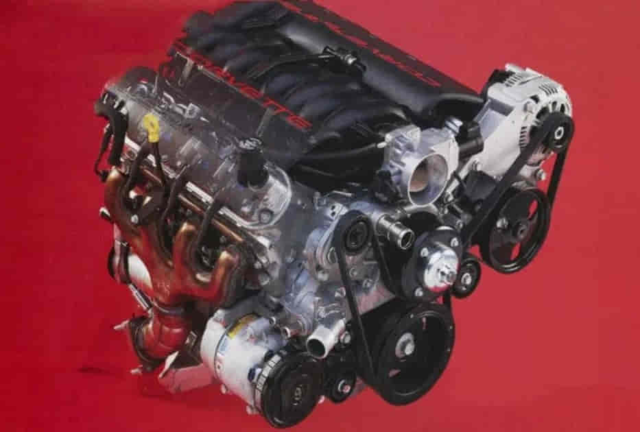
The LS1 firing order is 1-8-7-2-6-5-4-3, which defines the sequence in which the eight cylinders in the GM Chevrolet LS1 V8 engine deliver their power strokes. Knowing the correct firing order is important when diagnosing engine misfires, checking ignition components, or verifying engine specifications during maintenance and repair. However, the firing order is not the same as cylinder numbering, and confusing these two concepts can lead to incorrect diagnosis.
The Chevrolet LS1 is a Generation III small-block V8 engine used in vehicles such as the Chevrolet Corvette C5 and the Camaro and Pontiac Firebird equipped with the LS1. Its ignition system uses electronically controlled ignition coils rather than a traditional distributor, so understanding the firing sequence requires distinguishing the order of combustion from the physical locations of the ignition components.
This guide explains the LS1 firing order, how the cylinders are numbered, and how the ignition system follows the engine’s firing sequence. It also covers common symptoms associated with ignition-related misfires, diagnostic considerations, and differences between the LS1 and other GM V8 engines. These distinctions help owners and technicians identify the correct technical information for the engine they are working on.
What Is the Firing Order of a Chevy LS1 Engine?
The firing order of a Chevrolet LS1 V8 engine is 1-8-7-2-6-5-4-3. This sequence defines the order in which the eight cylinders deliver their power strokes during engine operation. The LS1 uses this firing order as part of its combustion cycle, with the crankshaft, camshaft, and electronic engine management system working together to coordinate valve operation and ignition timing. Using the correct firing order is essential when diagnosing engine performance problems or verifying LS1 engine specifications.
A firing order is different from cylinder numbering because it describes the sequence of combustion events rather than the physical location of each cylinder. On the LS1, cylinder 1 fires first in the sequence, followed by cylinder 8, cylinder 7, cylinder 2, cylinder 6, cylinder 5, cylinder 4, and cylinder 3. After the eighth event, the sequence repeats as the engine continues running. Because the LS1 is a four-stroke V8, each cylinder completes its operating cycle over two crankshaft revolutions, while the engine produces a power stroke every 90 degrees of crankshaft rotation under its evenly spaced firing sequence.
The LS1 firing order also matters when interpreting misfire data. For example, diagnostic trouble code P0301 identifies a misfire detected on cylinder 1, while P0308 identifies a misfire detected on cylinder 8. These codes refer to cylinder numbers, not positions in the firing sequence. A technician must identify the affected cylinder correctly before inspecting its spark plug, ignition coil, wiring, fuel delivery, or mechanical condition.
The LS1 uses an electronically controlled ignition system with individual ignition coils, rather than a traditional distributor that routes high voltage through a single coil and distributor cap. Therefore, the firing order should not be interpreted as a physical coil-installation sequence. When servicing an LS1, use the correct cylinder numbering and vehicle-specific service information to identify components and diagnose faults accurately. This distinction prevents confusion between the engine’s combustion sequence and the physical arrangement of its ignition components.
Read more: How to Force Regen on Duramax L5P
How Are the Cylinders Numbered on an LS1 Engine?
The Chevrolet LS1 V8 engine numbers its cylinders from the front of the engine to the rear, with odd-numbered cylinders on the driver’s side and even-numbered cylinders on the passenger’s side in typical left-hand-drive applications. Viewed from the driver’s seat, the driver-side bank is numbered 1-3-5-7, while the passenger-side bank is numbered 2-4-6-8. Cylinder 1 is at the front of the driver-side bank, closest to the engine’s front cover and crankshaft pulley. This numbering system identifies each cylinder’s physical location and is essential for maintenance and fault diagnosis.
The cylinder numbering system is separate from the LS1 firing order, which is 1-8-7-2-6-5-4-3. For example, cylinder 3 is the third cylinder in the driver-side bank when counted from the front, but it fires seventh in the combustion sequence. Likewise, cylinder 8 is at the rear of the passenger-side bank, yet it fires second in the sequence. Understanding this distinction prevents technicians from confusing a cylinder’s physical position with its place in the firing cycle.
Correct cylinder identification is particularly important when diagnosing misfire codes, replacing spark plugs, testing ignition coils, or inspecting wiring. For example, a diagnostic code P0305 indicates a misfire detected on cylinder 5, so the technician must locate cylinder 5 rather than count to the fifth event in the firing order. Because engine installation and vehicle orientation can affect how components appear from above, technicians should confirm the bank orientation using the service information for the specific vehicle before disconnecting or replacing parts.
How Does the LS1 Firing Order Work With the Ignition System?
The LS1 firing order, 1-8-7-2-6-5-4-3, coordinates combustion events with the engine’s crankshaft rotation, camshaft operation, and electronic ignition control. The LS1 uses a distributorless ignition system with an individual ignition coil for each cylinder. The engine control module (ECM) determines when each coil should fire based on inputs such as crankshaft position, camshaft position, engine speed, and operating load. This arrangement allows the ignition system to deliver a spark to the correct cylinder at the required point in its four-stroke cycle.
Each cylinder needs a spark near the end of its compression stroke to ignite the compressed air-fuel mixture. The crankshaft position sensor provides information about crankshaft position and speed, while the camshaft position sensor helps the ECM identify the engine’s operating cycle. Using these signals, the ECM controls ignition timing and coordinates spark delivery. Because the LS1 has eight cylinders with evenly spaced firing events, a power stroke occurs every 90 degrees of crankshaft rotation during normal operation. The firing order defines the sequence of these events, while ignition timing determines the precise crankshaft position at which each spark occurs.
The LS1’s individual coils also make cylinder-specific diagnosis more direct than on a traditional distributor-based ignition system. For example, if cylinder 7 misfires, a technician can inspect its spark plug, coil, electrical connector, and associated wiring without tracing a high-voltage lead through a distributor cap. However, the firing order alone does not identify the cause of a misfire. A fault may also involve fuel delivery, an air leak, compression, valve operation, or an electrical signal used by the ECM.
When servicing the ignition system, technicians should use the LS1 cylinder numbering diagram and the vehicle-specific wiring information to identify the correct coil and connector. The firing order is a combustion sequence, not a physical coil-installation pattern. Keeping these concepts separate helps prevent incorrect component identification and supports a more accurate diagnosis of ignition-related problems.
What Symptoms Can Occur When LS1 Ignition Components Are Connected Incorrectly?
Incorrect ignition component connections or damaged electrical connectors can cause an LS1 engine to misfire, run roughly, hesitate during acceleration, or become difficult to start. These symptoms occur when one or more cylinders fail to ignite the air-fuel mixture consistently or when the engine management system cannot control ignition as intended. The severity depends on the fault, the affected cylinder, and the engine’s operating conditions. In some cases, the check engine light illuminates and the ECM stores a diagnostic trouble code that identifies the cylinder where a misfire was detected.
A cylinder-specific misfire is one of the most useful clues when diagnosing an LS1 ignition problem. For example, code P0301 indicates a misfire detected on cylinder 1, while P0307 indicates a misfire detected on cylinder 7. These codes do not automatically prove that the ignition coil or spark plug is faulty; they identify the cylinder where the ECM detected a combustion problem. A technician should inspect the spark plug, ignition coil, connector, and wiring, then consider fuel delivery and mechanical causes if the ignition components test correctly.
Incorrectly installed or damaged ignition components can also cause hesitation under load, unstable idle, reduced engine performance, and increased fuel consumption. Under acceleration, a weak spark or an intermittent electrical connection may prevent reliable combustion when cylinder pressure rises. If unburned fuel enters the exhaust, it can also overheat and damage the catalytic converter. A flashing check engine light can indicate an active misfire severe enough to risk catalytic-converter damage, so the vehicle should not be driven hard and should be stopped safely if the engine runs severely rough.
Diagnosis should begin with confirming the LS1 firing order and cylinder numbering, followed by checking the condition and connections of the relevant ignition components. Because the LS1 uses individual ignition coils, technicians should identify the affected cylinder using the engine’s numbering diagram rather than assuming that the firing sequence represents the physical coil layout. If the firing order and connections are correct, further testing should examine spark quality, injector operation, compression, and other potential causes before replacing parts.
How Do You Diagnose an LS1 Misfire After Checking the Firing Order?
Diagnosing an LS1 misfire requires identifying the affected cylinder, testing its ignition components, and checking fuel delivery and mechanical condition if the ignition system is working correctly. The firing order is the starting point for confirming the engine’s combustion sequence, but it does not identify the cause of a misfire by itself. A systematic diagnosis helps technicians avoid replacing functional parts and makes it easier to isolate the fault.
The first step is to scan the engine control module for diagnostic trouble codes and identify whether the fault affects a specific cylinder or multiple cylinders. For example, P0304 indicates a misfire detected on cylinder 4, while P0300 indicates random or multiple-cylinder misfires. After recording the codes and relevant freeze-frame data, locate the affected cylinder using the LS1 numbering diagram. Freeze-frame data can help show the engine speed, load, and other operating conditions present when the fault was recorded, which may help distinguish an idle-related problem from one that occurs during acceleration.
The next step is to inspect the affected cylinder’s spark plug, ignition coil, electrical connector, and wiring. Look for a worn or damaged spark plug, a loose connector, corrosion, or visible wiring damage. If the vehicle-specific service procedure permits it, a technician can use appropriate tests or a controlled component swap to determine whether the fault follows a coil or spark plug to another cylinder. For example, if a misfire moves from cylinder 4 to cylinder 6 after a suitable coil swap, the coil becomes a stronger suspect. The test must be performed correctly, and the codes should be rechecked before drawing a conclusion.
If the ignition components pass inspection, the diagnosis should continue with fuel delivery and mechanical testing. An injector problem can prevent the affected cylinder from receiving the correct amount of fuel, while low compression or a valve-train fault can prevent the cylinder from producing normal power even when spark and fuel are present. Depending on the symptoms, further checks may include injector operation, compression testing, leak-down testing, and inspection for intake air leaks. If several cylinders misfire together, technicians should also consider shared causes such as fuel pressure, electrical supply, sensor signals, or an air leak affecting multiple cylinders.
A flashing check engine light with a severe misfire requires prompt attention because continued operation can damage the catalytic converter. Avoid heavy acceleration and stop driving if the engine runs severely rough; arrange professional diagnosis when needed. The most reliable approach is to confirm cylinder identity, inspect the ignition system, and then test fuel and mechanical systems in a logical order rather than assuming that every LS1 misfire results from an incorrect firing order.
Does the LS1 Firing Order Differ From Other GM LS Engines?
The LS1 firing order is 1-8-7-2-6-5-4-3, and this sequence is also used by several other engines in the GM LS family, including the LS6, LS2, LS3, and LS7. These engines share a firing sequence designed around their V8 architecture and crankshaft configuration. However, a shared firing order does not mean that every LS-family engine has identical ignition components, cylinder-head designs, engine controls, or service requirements. Engine-specific specifications should always be confirmed before carrying out repairs or modifications.
Cylinder numbering is also consistent across many conventional GM LS V8 applications. In typical left-hand-drive installations, cylinders 1, 3, 5, and 7 are arranged from front to rear on the driver’s side, while cylinders 2, 4, 6, and 8 are arranged from front to rear on the passenger’s side. This arrangement helps technicians locate cylinders when interpreting diagnostic trouble codes or inspecting ignition components. For example, a misfire code P0306 refers to cylinder 6, regardless of where that cylinder appears in the firing sequence. Vehicle-specific service documentation remains the best reference when working on an engine installed in an unusual configuration.
Although the firing order is shared across several LS engines, differences in engine management systems, ignition hardware, camshaft specifications, and wiring arrangements can affect diagnosis and repair procedures. A component or test procedure appropriate for an LS1 should not automatically be assumed to apply to every LS variant. For example, when replacing an ignition coil or diagnosing a misfire on an LS3, technicians should follow the wiring diagram and service specifications for that particular engine and vehicle.
For accurate maintenance, identify the exact engine variant before relying on a firing-order reference. The sequence 1-8-7-2-6-5-4-3 provides the essential combustion-order information for the LS1, while cylinder numbering identifies each cylinder’s physical location. Keeping these two concepts separate—and confirming the specifications for the exact engine—helps prevent diagnostic errors across the GM LS family.