The 4L60E check balls are located in specific hydraulic passages within the valve body and transmission case, where they control automatic transmission fluid (ATF) flow during gear changes. Their exact locations and quantity depend on the transmission’s model year, valve body configuration, and separator plate design. Correct placement is essential because a missing or incorrectly positioned check ball can disrupt hydraulic pressure and cause shifting problems.
The 4L60E transmission uses small check balls to open or block fluid passages as hydraulic pressure changes. These components work with the valve body, separator plate, and shift control circuits to regulate transmission operation. During valve body removal or transmission rebuilding, check balls can become dislodged, making an accurate location diagram necessary for reassembly.
There is no single check ball layout that applies to every 4L60E transmission. Production changes and aftermarket modifications can affect the required placement. Identifying the correct transmission configuration before installation helps prevent assembly errors and hydraulic circuit malfunctions.
This guide explains 4L60E check ball locations, check ball counts, diagram identification, model-year differences, and installation procedures. It also covers the functions of check balls, symptoms of incorrect placement, and signs of separator plate wear.
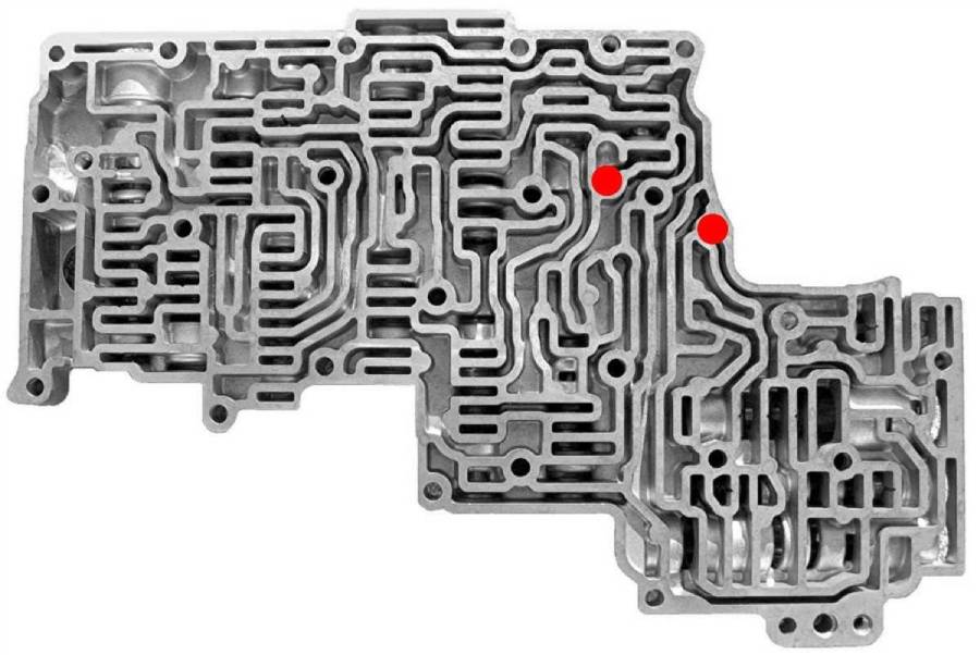
Where Are the Check Balls Located in a 4L60E Transmission?
The 4L60E check balls are positioned in designated pockets and hydraulic passages in the valve body assembly and transmission case. Their placement allows transmission fluid to flow through specific circuits while preventing reverse flow when hydraulic pressure changes. The exact locations depend on the transmission’s production year, separator plate design, and valve body configuration.
Most check ball locations become accessible after removing the transmission oil pan, filter, and valve body assembly. The separator plate sits between the valve body and transmission case, separating hydraulic circuits through precisely positioned openings. Each check ball must sit in its designated pocket so it can seal the correct passage under hydraulic pressure.
The main areas to inspect are:
- Valve body: Contains hydraulic passages and designated check ball seats that regulate fluid movement through the transmission’s control circuits.
- Transmission case: Contains additional hydraulic passages and check ball locations associated with the transmission’s internal fluid routing.
- Separator plate: Contains calibrated openings that interact with check balls and hydraulic passages. The plate must match the transmission configuration to maintain proper fluid control.
Check balls must be identified according to their seating locations rather than simply placed into visible holes. Bolt holes, fluid passages, and check ball pockets can appear similar when the valve body is disassembled. Installing a check ball in an incorrect opening can block a necessary hydraulic passage or prevent a circuit from sealing properly.
The separator plate is an essential reference for identifying correct check ball placement. Its openings must align with the appropriate valve body and case passages. A worn plate may also show circular impressions where check balls repeatedly contact their seating surfaces. These marks can help identify contact areas, but they should not replace a verified location diagram.
Before installing check balls, identify the transmission model year and compare the valve body and separator plate with the appropriate factory service documentation. Transmissions fitted with aftermarket shift kits or replacement valve bodies may require a different check ball arrangement from the original factory configuration.
How Many Check Balls Are in a 4L60E Transmission?
The number of check balls in a 4L60E transmission varies according to its hydraulic control configuration and installed modifications. Many factory-style 4L60E valve body arrangements use seven check balls in the valve body area and additional check balls in the transmission case. However, this arrangement should not be treated as a universal specification for every production year.
The total count must include all check balls required by the specific valve body, separator plate, and transmission case configuration. Counting only the balls found during valve body removal can produce an incorrect result because some check balls remain in separate locations or may have been removed during previous repairs.
| Component | Check ball information |
|---|---|
| Valve body | Many factory-style configurations use seven check balls; verify the specific layout |
| Transmission case | Additional check balls may be required depending on the configuration |
| Separator plate | Contains openings and seating surfaces associated with check ball operation |
| Aftermarket shift kit | May change the required number or placement according to kit instructions |
Production changes affect how transmission fluid moves through the hydraulic circuits. A separator plate from one configuration may have different openings or fluid routing requirements from another. Consequently, the check ball arrangement must correspond to the installed hydraulic components rather than the transmission name alone.
A missing check ball does not automatically indicate an assembly error. Certain aftermarket modifications intentionally eliminate specific check balls to change hydraulic circuit behavior. Conversely, an additional ball installed in a passage that should remain open can interfere with fluid flow and create transmission operating problems.
For an accurate count, compare the removed check balls with a configuration-specific diagram before reassembly. Record the positions of all existing check balls, inspect the separator plate for wear, and confirm whether the transmission contains factory or modified hydraulic components. This process helps prevent incorrect placement and avoids relying on an assumed check ball count.
How Do You Read a 4L60E Check Ball Location Diagram?
To read a 4L60E check ball location diagram, identify the diagram’s viewing orientation, locate the designated check ball seats, and match the illustrated hydraulic passages to the actual valve body and transmission case. A correct diagram shows where each check ball belongs relative to the separator plate, fluid channels, and valve body components.
Start by checking whether the diagram shows the valve body from the separator plate side or the opposite side. This distinction matters because the same assembly appears reversed when viewed from different directions. A check ball position shown near the left edge of one illustration may appear on the right when the component is flipped over.
Next, identify the reference points used in the diagram. Valve body bolt holes, casting shapes, solenoid locations, and hydraulic passages help establish the correct orientation. Use at least two recognizable reference points before matching a check ball position. This reduces the risk of interpreting a mirrored or incorrectly oriented illustration.
Check ball locations must be distinguished from ordinary hydraulic openings. A check ball seat is designed to support a ball and allow it to seal or redirect fluid flow under pressure. Other openings serve as feed passages, exhaust passages, or mounting holes and must remain unobstructed. The presence of a circular opening alone does not establish that a check ball belongs there.
The separator plate provides another reference because its calibrated openings correspond to specific hydraulic circuits. Check ball contact areas may show circular wear marks, particularly where repeated movement has affected the plate surface. However, previous assembly errors or aftermarket modifications can make these marks unreliable as the sole method of identifying placement.
How Do You Match a Check Ball Diagram to Your 4L60E Transmission?
Match a check ball diagram to your 4L60E transmission by verifying the model year, valve body configuration, separator plate identification, and installed modifications. These characteristics determine whether the diagram represents the hydraulic layout of the transmission being serviced.
The vehicle’s model year provides a starting point, but it does not always identify the installed transmission. A replacement transmission or rebuilt valve body may use components from a different production period. Inspect the actual assembly and compare its casting features, separator plate openings, and component arrangement with the applicable service documentation.
Follow this identification sequence:
- Identify the transmission: Confirm that the installed unit is a 4L60E and establish its production information where available.
- Inspect the valve body: Compare casting features, hydraulic passage arrangements, and component locations with the reference diagram.
- Identify the separator plate: Check its markings and opening pattern against the specified configuration.
- Check for modifications: Determine whether an aftermarket shift kit, replacement valve body, or modified separator plate has changed the required check ball arrangement.
- Verify the orientation: Align the diagram with the physical assembly before positioning any check balls.
Use the factory service manual for an unmodified transmission or the applicable manufacturer’s installation instructions for a modified assembly. A generic 4L60E diagram is insufficient when its configuration cannot be matched to the installed components.
How Do 4L60E Check Ball Locations Differ by Year?
4L60E check ball locations differ between certain production configurations because GM revised the transmission’s valve body, separator plate, and hydraulic control system during its production history. These changes affect fluid routing and can alter which check ball positions are required. Therefore, a diagram from one production period should not automatically be applied to another.
The 4L60E was introduced for the 1993 model year and underwent several hydraulic and electronic control revisions. Changes to valve body components and separator plate designs were introduced to support updated shift control characteristics and transmission operation. However, not every production change altered check ball placement, so each configuration must be verified individually.
The following table identifies useful production groups for researching the correct hydraulic layout. These ranges are identification references, not a definitive check ball location chart.
| Model years | Configuration considerations |
|---|---|
| 1993–1994 | Early 4L60E hydraulic control configuration; use the corresponding early service documentation |
| 1995 | Transitional configuration requiring specific valve body and separator plate identification |
| 1996–2000 | Later hydraulic control revisions; verify the installed plate and valve body |
| 2001–2006 | Additional production and application differences; check the exact assembly |
| 2007 and later | Later applications and related transmission variants require configuration-specific documentation |
The differences between these groups should be established using the applicable GM service information or verified transmission component documentation. The table does not establish that every year range has a different number of check balls.
Separator plate compatibility is particularly important when identifying year-specific check ball locations. The plate contains calibrated openings that determine how transmission fluid moves between hydraulic passages. Installing a plate with an incompatible opening pattern can change fluid routing even when the check balls appear to occupy the expected positions.
Vehicle applications also matter. A 4L60E installed in a Chevrolet Silverado may not have an identical hydraulic control configuration to one used in a Chevrolet Corvette from a different production period. Transmission replacements and aftermarket modifications introduce further differences.
For this reason, identify the actual transmission components before selecting a check ball diagram. Model-year information should narrow the search, while valve body and separator plate identification should determine the final reference.
Can You Use the Same Check Ball Diagram for a 4L60E and 4L65E?
A 4L60E check ball diagram should only be used for a 4L65E when the relevant valve body, separator plate, and hydraulic circuit configurations are confirmed to match. Although the transmissions belong to the same GM automatic transmission family and share several design characteristics, their internal specifications and application-dependent components are not universally interchangeable.
The 4L65E was developed as a higher-capacity variation of the 4L60E, incorporating changes intended to support increased torque capacity. Shared transmission architecture does not guarantee identical check ball placement across every production year or vehicle application.
Before using a diagram across these transmission models, compare the separator plate opening pattern, valve body casting, hydraulic passages, and any aftermarket modifications. A matching external appearance is not sufficient evidence that the internal fluid routing is identical.
When the configurations differ or cannot be verified, use the service information specific to the installed transmission. This prevents incorrect check ball placement and reduces the risk of hydraulic control problems after reassembly.
How Do You Install Check Balls in a 4L60E Transmission?
To install check balls in a 4L60E transmission, identify the correct hydraulic configuration, inspect the valve body and separator plate, position each check ball in its designated seat, and verify the complete arrangement before reassembly. The installation must follow a configuration-specific diagram because incorrect placement can block hydraulic passages, create internal fluid leaks, and interfere with transmission shifting.
Begin with the vehicle safely supported, the engine off, and the transmission fluid drained according to the applicable service procedure. Remove the transmission oil pan and filter to access the valve body assembly. Before disconnecting electrical components or removing the valve body, document their original positions and consult the factory service manual for the correct removal sequence.
Prepare a clean work surface and organize the removed components to prevent contamination or accidental loss. Check balls are small and can fall out when the valve body or separator plate is separated from the transmission case. Record their original positions whenever possible, but do not assume a previously assembled transmission has the correct arrangement.
Inspect each check ball before installation. Its surface should be smooth and free from pitting, flattening, cracks, or excessive wear. Examine the corresponding seating surfaces and separator plate openings for deformation or damage. A worn check ball seat can allow hydraulic fluid to bypass the intended sealing point, reducing the circuit’s ability to maintain pressure.
Place each check ball into the location specified by the verified diagram. Check ball positions must correspond to the installed valve body and separator plate rather than an assumed universal 4L60E layout. Do not install extra check balls in unused passages or omit required balls based solely on a different model-year illustration.
During assembly, maintain the specified orientation of the components and prevent check balls from moving out of their seats. Use only assembly aids permitted by the applicable service instructions. Unapproved grease, adhesive, or other materials can contaminate hydraulic passages or interfere with check ball movement.
After confirming the placement, reinstall the separator plate, gaskets, and valve body according to the correct service procedure. Use the specified bolt tightening sequence and torque values for the exact transmission configuration. Incorrect tightening can distort components or compromise hydraulic sealing. Reconnect the electrical components, reinstall the filter and oil pan, and refill the transmission with the specified automatic transmission fluid.
How Do You Verify 4L60E Check Ball Placement Before Reassembly?
Verify 4L60E check ball placement by comparing every installed ball with the correct location diagram and checking the condition and alignment of the surrounding hydraulic components. This inspection should occur before the separator plate and valve body are secured because misplaced check balls become difficult to identify after assembly.
Complete the following five checks:
- Confirm the check ball count. Compare the number of installed check balls with the configuration-specific service documentation, including any required transmission case locations.
- Inspect every seating position. Verify that each ball rests in its designated pocket and that no ball has entered an unrelated fluid passage or bolt hole.
- Check the separator plate. Inspect the plate for worn openings, deformation, and damage around check ball contact areas.
- Verify component compatibility. Confirm that the valve body, separator plate, and gaskets match the required hydraulic configuration and any installed shift kit instructions.
- Confirm assembly alignment. Ensure the check balls remain seated and the separator plate and gaskets are correctly positioned before tightening the valve body.
A correctly installed check ball arrangement allows the hydraulic circuits to operate according to their intended design. However, correct placement alone does not establish that the transmission is free from hydraulic or mechanical faults. Worn valves, damaged seals, solenoid failures, and internal clutch problems can produce similar shifting symptoms.
Once reassembly is complete, check the transmission fluid level using the specified procedure and inspect for leaks. Verify transmission operation according to the manufacturer’s service instructions. Any abnormal engagement, slipping, or shifting behavior requires further diagnosis rather than assuming the check ball installation is correct.
What Do Check Balls Do in a 4L60E Transmission?
Check balls in a 4L60E transmission control hydraulic fluid flow by opening or sealing specific passages in the valve body and transmission case. They act as pressure-responsive valves that help direct automatic transmission fluid (ATF) through the hydraulic circuits responsible for clutch application, release, and gear changes.
Each check ball moves according to the pressure difference across its seating surface. When fluid pressure pushes a ball against its seat, the ball restricts or blocks flow through that passage. When pressure acts from the opposite direction with sufficient force, the ball moves away from its seat, allowing fluid to pass. This operation helps control fluid direction and pressure distribution without requiring a separate electronic actuator for each passage.
The 4L60E hydraulic control system combines check balls with shift solenoids, spool valves, accumulators, and the separator plate. The powertrain control module (PCM) commands the shift solenoids, while the valve body routes pressurized fluid to the appropriate transmission components. Check balls support this process by controlling flow through designated hydraulic circuits.
Check ball placement directly affects hydraulic circuit operation. For example, a ball that fails to seal its intended passage can allow fluid to escape through an unintended route, potentially reducing the pressure available to apply a clutch. Conversely, a ball installed in a passage designed to remain open can restrict fluid movement and interfere with the intended shift sequence.
The separator plate also influences check ball operation because its calibrated openings determine how fluid passes between the valve body and transmission case. Proper interaction between these components supports predictable hydraulic response during transmission operation.
Read more: How to Fix Tesla Not Locking When You Walk Away
What Happens If a 4L60E Check Ball Is Missing or Installed Incorrectly?
A missing or incorrectly installed 4L60E check ball can cause delayed gear engagement, slipping, harsh shifts, or incorrect hydraulic circuit operation. The specific symptoms depend on which check ball is affected and how its location influences fluid pressure and flow. Not every missing check ball produces the same transmission problem, and some aftermarket modifications intentionally change the original arrangement.
When a required check ball is missing, hydraulic fluid may flow through a passage that should be sealed during a particular operating condition. This can reduce pressure within the affected circuit or change the timing of clutch application. Insufficient clutch apply pressure can cause slipping, while altered fluid routing can interfere with the normal transition between gears.
An incorrectly positioned check ball creates a different problem. If a ball blocks a passage intended to remain open, fluid delivery to a transmission component may become restricted. Depending on the affected circuit, this can delay clutch application, disrupt release timing, or produce abnormal shifting behavior.
The following table summarizes potential symptoms and their hydraulic explanations.
| Symptom | Possible check ball-related cause |
|---|---|
| Delayed engagement | Fluid leakage or restricted flow in an affected apply circuit |
| Transmission slipping | Insufficient clutch apply pressure associated with incorrect hydraulic routing |
| Harsh shifting | Altered fluid flow or clutch apply timing |
| Missing or abnormal gear changes | A hydraulic passage is incorrectly blocked or left open |
| Inconsistent shifting after valve body service | Incorrect check ball placement, separator plate alignment, or gasket installation |
These symptoms are not exclusive to check ball problems. Worn clutch packs, defective shift solenoids, valve body wear, internal seal leakage, and incorrect transmission fluid levels can produce similar operating conditions. A symptom alone cannot establish that a check ball is missing or misplaced.
Incorrect check ball placement should be investigated when shifting problems begin immediately after valve body removal, separator plate replacement, or transmission rebuilding. The timing of the problem provides useful diagnostic context because these procedures directly involve components that determine check ball positioning.
Begin diagnosis by checking the transmission fluid level and condition, retrieving applicable diagnostic trouble codes, and reviewing the repair history. If the problem appeared after valve body service, compare the installed check ball arrangement with the correct configuration-specific diagram. Inspect the separator plate and gaskets for misalignment, damaged sealing surfaces, or incorrect hydraulic passage coverage.
Avoid repeatedly operating a transmission that exhibits significant slipping or abnormal engagement. Continued clutch slippage generates heat and friction material debris, which can damage additional internal components. Correcting the underlying hydraulic fault promptly helps limit further transmission damage.
How Can You Tell If a 4L60E Check Ball or Separator Plate Is Worn?
A worn 4L60E check ball or separator plate can be identified by surface damage, enlarged check ball seating areas, and visible deformation around hydraulic passage openings. These defects can prevent check balls from sealing correctly, allowing automatic transmission fluid to leak between hydraulic circuits and potentially affecting clutch apply pressure and shift performance.
Check ball wear appears as flattening, pitting, scratches, or irregularities on the ball’s surface. A properly functioning check ball requires a smooth, consistent contact surface to seal against its seat. Surface damage can create small leakage paths that allow pressurized fluid to bypass the intended hydraulic restriction. Inspect each ball under adequate lighting and compare its condition with the applicable service specifications.
Separator plate wear commonly develops where repeated check ball contact deforms the metal around a seating opening. Over time, hydraulic pressure repeatedly forces the ball against the plate, creating a circular indentation. Excessive wear can enlarge or distort the opening, allowing the ball to sit deeper than intended or become lodged in the plate. Severe deformation can interfere with fluid control and contribute to transmission shifting problems.
Inspect the separator plate for three primary signs of damage: enlarged check ball openings, deep circular indentations, and cracks or deformation around hydraulic passages. Also examine the surrounding gasket surfaces for damage that could create additional fluid leakage paths. Minor contact marks do not automatically indicate component failure, so replacement decisions should follow the applicable inspection criteria.
When Should You Replace a 4L60E Check Ball or Separator Plate?
Replace a 4L60E check ball when it has visible surface damage, an incorrect diameter, or wear that prevents proper seating. Replace the separator plate when its check ball openings are excessively enlarged, cracked, distorted, or damaged beyond the manufacturer’s service limits. Reusing defective components can leave hydraulic leakage problems unresolved even when every check ball is installed in the correct location.
Check ball material and dimensions must match the transmission’s hydraulic configuration. Factory components and aftermarket repair kits may use different check ball specifications, so replacement parts should be selected using the applicable service documentation or kit instructions. Installing an incorrectly sized ball can change its seating behavior and restrict or expose hydraulic passages.
A damaged separator plate requires particular attention because replacing the check ball alone will not restore a deformed seating surface. When the plate has excessive wear, install a compatible replacement or an approved repair solution that addresses the affected opening. Verify separator plate identification, gasket compatibility, and check ball requirements before reassembly.
After replacing worn components, confirm the complete check ball arrangement against the correct diagram and follow the specified valve body installation procedure. Proper component condition, accurate placement, and correct hydraulic sealing are all necessary for reliable 4L60E transmission operation.