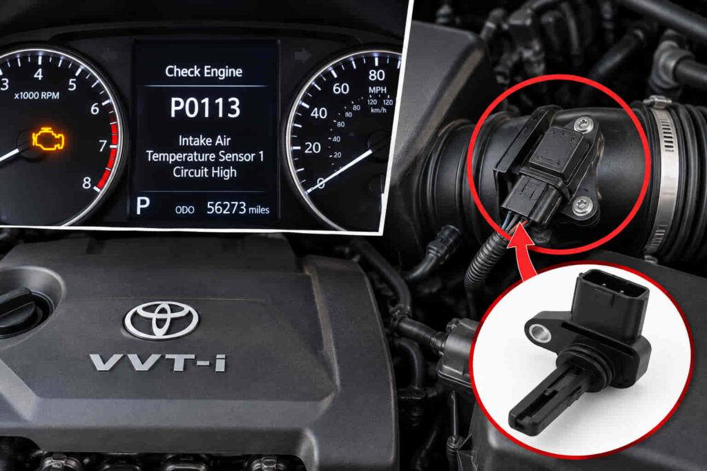
Toyota code P0113 indicates an Intake Air Temperature Sensor 1 Circuit High Input condition, meaning the engine control module has detected an IAT circuit signal outside its expected high range. “Circuit high” does not simply mean the intake air is too hot. It describes an electrical condition in the intake air temperature sensor circuit, so diagnosis must focus on the sensor signal and circuit rather than assuming the engine is receiving excessively hot air.
The IAT sensor provides temperature information that the engine control system uses when calculating operating strategies. A P0113 fault can develop when the IAT sensing element fails, the electrical connector is disconnected or has poor terminal contact, or the wiring creates an open or abnormal signal condition. Depending on the Toyota model, model year, and engine, the IAT sensing function may also be incorporated into another air-measurement assembly, so sensor location and circuit configuration should be verified for the specific vehicle.
Replacing an IAT or MAF-related component without testing the circuit can leave P0113 unresolved when the actual problem is a connector or wiring fault. A proper diagnosis uses the stored code, freeze-frame information, live IAT data, visual inspection, and electrical testing to determine where the high-input condition originates. This guide explains what Toyota P0113 means, its causes and symptoms, how to diagnose the IAT sensor circuit, and how to repair and verify the actual fault.
What Does the P0113 Code Mean on a Toyota?
Toyota code P0113 means Intake Air Temperature Sensor 1 Circuit High Input. The code is stored when the engine control system detects an electrical input from the intake air temperature sensor circuit that is outside the expected high range under the applicable diagnostic conditions. The fault therefore points to the IAT sensing circuit and should be diagnosed as an electrical or sensor-related condition rather than interpreted only as an abnormal air-temperature reading.
The intake air temperature sensor provides information about the temperature of the air entering the engine. The engine control module uses this information as part of its engine-management calculations because air temperature affects air density and operating conditions. The IAT reading is therefore not an isolated dashboard measurement; it is an input used by the control system when determining how the engine should operate.
The IAT sensing element commonly changes electrical resistance as temperature changes. The control module interprets the resulting circuit signal as an intake-air-temperature value. If a sensor, connector, or wiring fault causes the signal to move beyond the range expected by the diagnostic strategy, the ECM can recognize the condition as a circuit fault and store P0113.
An open electrical path is particularly relevant to P0113 diagnosis. A disconnected sensor connector, damaged wire, poor terminal connection, or failed sensing element can alter the circuit so that the ECM sees a high-input condition. This is why P0113 should not automatically lead to sensor replacement. The sensor is one component in a circuit that also includes its connector, terminals, wiring, and control-module connection.
The physical location of the IAT sensing element also varies between Toyota applications. On some configurations, intake-air-temperature sensing can be incorporated into an air-measurement assembly rather than provided by an identical standalone sensor in every model. The Toyota model, model year, engine, and applicable wiring information should therefore be established before locating the sensor or testing specific terminals.
P0113 ultimately identifies the type of circuit condition the ECM has detected, not the component that must automatically be replaced. The code narrows diagnosis to the IAT Sensor 1 circuit, while testing determines whether the root cause is the sensing element, connector, wiring, or another part of that electrical path.
Does Toyota P0113 Mean the Intake Air Temperature Is Too High?
No. Toyota P0113 does not simply mean that the intake air temperature is too high. The word “high” in P0113 refers to the electrical input condition detected in the Intake Air Temperature Sensor 1 circuit. Confusing circuit input with physical air temperature reverses the diagnostic meaning of the code and can send troubleshooting in the wrong direction.
The distinction becomes clearer when the electrical behavior of an IAT thermistor is considered. In a typical negative-temperature-coefficient temperature-sensing circuit, sensor resistance decreases as temperature rises and increases as temperature falls. The ECM interprets the electrical behavior of this circuit and converts it into a calculated temperature value. The relationship between temperature and signal therefore has to be understood through the circuit design rather than by reading “high input” as “high temperature.”
A high-input fault can consequently produce an intake-air-temperature value on scan data that appears implausibly cold rather than extremely hot. An open sensor circuit or disconnected connector can create this type of diagnostic pattern in applicable circuit designs because the electrical signal moves toward the high side while the ECM interprets that condition as a very low temperature. The exact value and circuit behavior should be confirmed against the Toyota-specific diagnostic information rather than treated as a universal numerical specification.
This relationship makes live data useful during diagnosis. If the engine has been sitting long enough to approach ambient conditions, an IAT reading that is physically implausible compared with the surrounding temperature provides evidence that the sensor circuit is not reporting normally. The reading alone does not establish whether the sensor, connector, or wiring has failed, but it helps confirm that P0113 represents an actual circuit-data problem.
The same distinction prevents unnecessary work on the air-intake system. P0113 does not by itself prove that the engine compartment is too hot, that incoming air needs to be cooled, or that a mechanical intake restriction is responsible. Diagnosis should instead establish why the ECM is receiving a high electrical input from the IAT circuit.
Understanding “Circuit High” correctly creates the diagnostic boundary for the rest of the repair. Once P0113 is recognized as an electrical input condition rather than a literal high-temperature warning, testing can move logically toward the IAT sensing element, connector, terminals, wiring, and related circuit integrity instead of treating intake-air temperature itself as the root cause.
Read more: What Cars Have CVT Transmissions
Where Is the IAT Sensor Located on a Toyota?
The Toyota Intake Air Temperature sensor is located in the engine’s air-intake measurement path, but its exact position depends on the model, model year, engine, and sensor configuration. On some Toyota applications, the IAT sensing element is incorporated into the Mass Air Flow sensor assembly, while other configurations can use a different arrangement. The sensor location should therefore be confirmed for the specific vehicle before a component is disconnected, tested, or replaced.
The location of the sensing element follows its function. The engine control system needs information about the temperature of incoming air, so the IAT sensor must measure air associated with the engine’s intake path. However, this functional relationship does not mean every Toyota places a separate temperature sensor in the same physical location. Manufacturers can combine multiple sensing functions into one assembly when the engine-management design supports that configuration.
An IAT element integrated into a MAF sensor is particularly important during P0113 diagnosis because the technician may not find a separately replaceable component labeled only as an intake air temperature sensor. In that configuration, the electrical connector associated with the air-measurement assembly can contain circuits serving more than one sensing function. A P0113 fault can therefore require diagnosis of the IAT portion of that assembly and its wiring rather than assuming the entire MAF measurement function has failed.
Sensor integration also explains why replacement information must match the vehicle. If the IAT element is part of another sensor assembly, the applicable repair may differ from a Toyota that uses a separately serviceable IAT sensor. Model-specific wiring diagrams and component information establish the connector terminals, circuit routing, specifications, and serviceable component for the engine being diagnosed.
The safest diagnostic approach is to identify the exact Toyota configuration before electrical testing. Model year and engine information should be matched to the applicable service information, then the IAT Sensor 1 circuit can be traced from the sensing element through its connector and wiring toward the ECM. This prevents a generic sensor-location diagram from directing diagnosis toward a component that the specific engine does not use in the same form.
What Causes a P0113 Code on a Toyota?
Toyota P0113 is caused when a fault makes the ECM detect an abnormally high electrical input in the Intake Air Temperature Sensor 1 circuit. The root cause can be a failed IAT sensing element, disconnected or poorly connected electrical connector, damaged terminal, open or damaged wiring, or another fault affecting the integrity of the IAT circuit. A control-side problem is also possible but should not be assumed before the sensor and external circuit have been tested.
A disconnected connector is a strong diagnostic candidate because opening the IAT circuit can move its signal toward the condition interpreted by the ECM as circuit high. This can occur after work around the air-intake system if an electrical connector is left disconnected or does not fully engage during reassembly. Inspecting recent service work is therefore useful when P0113 appears immediately after an air-filter, intake, MAF-related, or other under-hood procedure involving the relevant area.
Connector and terminal faults can create a similar electrical condition even when the connector appears to be attached. A backed-out terminal, poor terminal tension, corrosion, contamination, or physical connector damage can interrupt the electrical path between the sensor and the wiring harness. The circuit can then behave as though the sensing element were disconnected. Visual inspection should consequently include the condition of the terminals and connection, not only whether the connector housing is plugged in.
Wiring damage can produce P0113 when continuity is lost in the relevant IAT circuit. A conductor can break internally, insulation can be damaged, or the harness can be affected by vibration, heat, previous repairs, or physical contact with surrounding components. The location of visible harness damage can provide evidence, but electrical testing is needed when the conductor appears normal externally and the open condition exists inside the insulation or at a terminal.
The IAT sensing element itself can also fail. Because the ECM derives temperature information from the electrical behavior of the sensing circuit, an internal sensor failure that creates an open or out-of-range condition can produce P0113. Sensor replacement becomes justified when testing shows that the circuit and connections are intact but the sensing element does not behave according to the applicable Toyota specifications.
A fault should not be assigned to the MAF sensor solely because the IAT element is integrated into the same assembly on a particular Toyota. The relevant question is whether the IAT sensing circuit within that configuration is producing the P0113 condition. MAF airflow measurement and IAT measurement are related through their physical assembly on some vehicles but remain distinct sensor functions for diagnostic purposes.
A control-module fault is a substantially different diagnosis and should be considered only after the external circuit has been verified according to the applicable service information. Replacing an ECM before establishing sensor, connector, terminal, and wiring integrity reverses the diagnostic order and risks replacing an expensive working component.
The cause of Toyota P0113 should therefore be identified by locating where the IAT circuit changes from normal operation to the high-input condition. This circuit-based approach distinguishes a failed sensor from an open connector or wiring fault and prevents P0113 from becoming an automatic instruction to replace whichever intake sensor is easiest to access.
What Are the Symptoms of Toyota Code P0113?
The most direct symptom of Toyota code P0113 is an illuminated Check Engine Light accompanied by the stored Intake Air Temperature Sensor 1 Circuit High Input fault. Drivability symptoms are less consistent because the effect of an abnormal IAT signal depends on the Toyota model, engine-management strategy, operating conditions, and whether other faults are present at the same time.
When the ECM determines that the IAT signal is outside its expected range, it cannot rely on that input in the same way it would during normal operation. The control system may respond by using a substitute or fail-safe value according to its programmed strategy. This allows the engine-management system to continue operating even though the measured intake-air-temperature information is no longer considered reliable.
A driver may therefore have a Toyota that starts and runs while P0113 remains stored. The absence of severe drivability symptoms does not prove that the fault has corrected itself because the ECM can compensate for an invalid sensor input. The Check Engine Light and abnormal scan data can remain the primary evidence of the circuit problem even when the vehicle feels normal during everyday driving.
When drivability changes do occur, they result from the loss or distortion of temperature information used by the engine-management system rather than from the P0113 code itself acting as a mechanical failure. Intake-air temperature contributes to the ECM’s understanding of current operating conditions, so an implausible signal can affect calculations associated with engine operation. The exact effect should be evaluated from vehicle-specific symptoms and scan data instead of assuming that every P0113 case produces rough idle, difficult starting, reduced performance, or increased fuel consumption.
The conditions under which the code appeared also provide diagnostic value. Freeze-frame data can show engine and operating information recorded when the ECM set the fault. Comparing that information with current IAT live data can help determine whether the temperature signal is plausible or whether it remains at an abnormal value that supports an open-circuit or sensor-related diagnosis.
Additional diagnostic trouble codes can change the interpretation as well. If P0113 appears with other air-measurement, electrical, or sensor-related codes, those faults should be considered together rather than diagnosed as unrelated problems automatically. Multiple codes sharing a connector, wiring area, electrical path, or recent service event can provide stronger evidence about the root cause than P0113 considered in isolation.
The symptom pattern for Toyota P0113 should therefore be interpreted from the combination of the Check Engine Light, stored and pending codes, freeze-frame information, live IAT data, and actual engine behavior. A vehicle that appears to drive normally still requires diagnosis because normal drivability does not restore the electrical integrity of the IAT circuit.
Can a Dirty or Bad MAF Sensor Cause Toyota P0113?
A bad MAF sensor assembly can be related to Toyota P0113 when the Intake Air Temperature sensing element is integrated into that assembly, but P0113 does not automatically mean the Mass Air Flow sensor is bad. The code specifically identifies a high-input condition in the IAT Sensor 1 circuit, so diagnosis must isolate the temperature-sensing function and its electrical path before the complete MAF assembly is condemned.
The distinction between MAF and IAT functions is important. The Mass Air Flow sensor measures information related to incoming air mass, while the Intake Air Temperature sensor provides information about air temperature. Toyota can package these sensing functions within the same physical assembly on applicable engines, but sharing a housing or connector does not make the two measurements diagnostically identical.
An internal failure affecting the IAT portion of an integrated sensor assembly can produce P0113 even if the diagnostic problem is specifically associated with temperature sensing. In that situation, replacement requirements depend on how the component is serviced. If the IAT sensing element is not separately serviceable from the applicable assembly, confirming an internal IAT failure can ultimately lead to replacement of the complete component. That decision should follow testing rather than the assumption that a MAF-related housing means the MAF function itself caused the code.
The electrical connector deserves equal attention because an integrated assembly can place multiple sensor circuits in the same connection point. A loose connector, damaged terminal, corrosion, or wiring problem affecting the IAT circuit can generate P0113 without an internal sensor failure. Replacing the complete sensor assembly in that situation leaves the actual wiring or connection problem unresolved.
Dirt on a MAF sensing element should not be treated as a universal explanation for P0113. P0113 describes an electrical high-input condition in the IAT circuit, so evidence of contamination must be connected to the actual fault mechanism before it is considered the root cause. Cleaning a MAF sensor without confirming why the IAT circuit is reporting high input is not a substitute for electrical diagnosis.
Recent work around the MAF sensor or air-intake system can nevertheless provide an important clue. If P0113 appears immediately after an air filter replacement, intake repair, sensor service, or another procedure in the same area, the relevant connector and harness should be inspected for incomplete connection, terminal damage, or disturbed wiring. The timing of the fault can help prioritize inspection without proving which component has failed.
The correct diagnostic question is therefore not simply whether a Toyota has a dirty or bad MAF sensor. It is whether the IAT sensing function is integrated into the applicable assembly and, if so, whether the P0113 high-input condition originates inside that component or elsewhere in its circuit. Establishing that distinction prevents unnecessary MAF replacement and keeps the diagnosis centered on the entity actually identified by P0113: the Intake Air Temperature Sensor 1 circuit.
How Do You Diagnose a Toyota P0113 Code?
Diagnosing Toyota P0113 starts by confirming the code and determining whether the Intake Air Temperature Sensor 1 data is plausible for the vehicle’s actual operating conditions. The goal is to identify where the IAT circuit develops the high-input condition, not to replace the sensor simply because P0113 names the IAT circuit.
A scan tool should first be used to confirm P0113 and check for additional diagnostic trouble codes. Related codes can provide important context because several faults appearing together may indicate a shared connector, wiring problem, electrical condition, or recent service issue. Freeze-frame data should also be reviewed because it records operating information associated with the conditions under which the ECM detected the fault.
The IAT live-data value should then be compared with realistic temperature conditions. When the vehicle has been parked long enough for engine and intake temperatures to approach ambient temperature, the IAT reading should be physically plausible for the surrounding environment. A reading that remains at an extreme or impossible value provides stronger evidence of an electrical or sensor fault than a reading that changes logically with actual intake-air temperature.
The next diagnostic step is a physical inspection of the relevant IAT circuit. The sensor or applicable integrated sensor assembly should be located using information for the exact Toyota model, model year, and engine. Its connector should be checked for complete engagement, damaged locking features, corrosion, contamination, bent or backed-out terminals, and other conditions that can interrupt the electrical path.
The wiring between the sensor and ECM should also be inspected for evidence of damage. Harness sections near the air-intake system can be affected by previous repairs, movement, heat, abrasion, or improper routing. Visible damage provides a useful diagnostic lead, but a wire that looks intact externally can still have an internal conductor or terminal fault. Electrical testing becomes necessary when visual inspection does not explain the high-input condition.
A useful diagnostic distinction can be made by observing how scan data responds when the circuit is inspected or tested according to the applicable Toyota procedure. If the IAT reading changes when a connector, circuit, or known test condition is manipulated, that response helps identify which portion of the system remains capable of communicating with the ECM. The exact test method, connector terminals, and expected values must come from service information for the specific vehicle because Toyota circuit configurations are not universal.
Sensor resistance or circuit voltage can then be tested when required by the applicable diagnostic procedure. An IAT thermistor should respond predictably as temperature changes, while the surrounding electrical circuit must provide the conditions required for the ECM to interpret that response. A measurement outside the specified range can support a sensor or circuit diagnosis, but it should be compared with the correct temperature and vehicle-specific specification rather than a generic value taken from another Toyota engine.
The ECM should become a suspect only after the sensor, connector, terminals, and external wiring have been verified. This diagnostic order matters because an open connector or damaged wire can produce the same code without any control-module failure. Replacing the ECM before proving circuit integrity introduces cost without establishing the root cause.
A successful P0113 diagnosis therefore ends with evidence that identifies the failed part of the circuit. The evidence may point to the IAT sensing element, an integrated sensor assembly, a connector terminal, or damaged wiring. Once the high-input condition has been isolated, the repair can address the actual fault instead of treating P0113 as an automatic component-replacement instruction.
How Do You Use Live Data to Diagnose Toyota P0113?
Live data helps diagnose Toyota P0113 by showing the intake air temperature value the ECM is interpreting from the IAT circuit. An implausible IAT reading can confirm that the circuit is not representing actual air temperature correctly and can provide a direction for further electrical testing.
The most useful comparison is made when the vehicle has been sitting long enough for its temperatures to stabilize near ambient conditions. Under those circumstances, the intake air temperature should be reasonably consistent with the environment around the vehicle. The reading does not need to match an external thermometer perfectly, but a major physical inconsistency indicates that the sensor signal deserves investigation.
An extremely cold IAT reading is particularly relevant when diagnosing a circuit-high code. In a typical negative-temperature-coefficient IAT circuit, an open circuit can cause the electrical signal to move toward the high side while the ECM interprets that signal as extremely low temperature. This is why a scan tool can display an implausibly cold temperature even though the diagnostic description contains the words “Circuit High Input.”
Live data becomes more useful when it is observed dynamically rather than read once. If the IAT value remains fixed at an implausible extreme despite changing conditions, the circuit may not be providing a valid sensor signal. If the value changes suddenly when the connector or nearby harness is carefully inspected, an intermittent connection or wiring fault becomes a stronger diagnostic possibility.
Comparison with other temperature information can provide additional context. After a sufficiently long cold soak, intake-air and other relevant temperature readings should reflect the fact that the vehicle has been exposed to the same general environment. A large unexplained difference can help identify an IAT reading that is not physically credible. This comparison should be used as diagnostic evidence rather than as a universal requirement that two sensors display identical temperatures.
Live data can also help verify a repair. After the confirmed connector, wiring, or sensor fault has been corrected, the IAT parameter should return to a plausible value and respond logically as operating conditions change. The code can then be cleared according to the appropriate procedure and the vehicle rescanned to determine whether P0113 returns.
Scan data does not identify the failed component by itself. An abnormal IAT value shows what the ECM is receiving, while connector inspection and electrical testing determine why it is receiving that value. Combining these two types of evidence turns the P0113 code from a general circuit description into a specific diagnosis of the sensor, connector, wiring, or related electrical path.
How Do You Test the Toyota IAT Sensor and Circuit?
Testing a Toyota IAT sensor and circuit requires verifying that the sensing element changes electrically with temperature and that the wiring between the sensor and ECM can transmit a valid signal. The exact connector terminals, resistance specifications, voltage values, and test procedures depend on the Toyota model, model year, and engine, so vehicle-specific service information should be used before making electrical measurements.
The diagnostic process should begin with the IAT live-data behavior already observed on the scan tool. If the displayed intake air temperature is physically implausible, electrical testing can determine whether the abnormal value originates in the sensor or elsewhere in the circuit. This connection between scan data and electrical measurements is important because a scan tool shows what the ECM interprets, while a multimeter can help establish what is happening at the sensor and wiring.
An IAT sensor commonly uses a thermistor whose resistance changes with temperature. In a negative-temperature-coefficient thermistor, resistance is higher at lower temperatures and decreases as temperature rises. Testing the sensing element therefore requires comparing its electrical behavior with the temperature conditions and specifications provided for the applicable Toyota. A resistance measurement without temperature context is incomplete because the expected resistance changes with sensor temperature.
The connector and terminals should also be evaluated as part of the circuit rather than treated as passive hardware. A terminal that is loose, corroded, damaged, pushed back, or unable to maintain proper contact can interrupt the IAT circuit and create a high-input condition. A connector can appear fully installed while an individual terminal fails to make a reliable electrical connection, so terminal condition matters when P0113 remains present despite an apparently normal connector.
Wiring integrity must be verified when the sensor and connector do not explain the fault. Continuity testing can help identify an open conductor, while additional circuit tests can determine whether the relevant wiring has an unintended electrical condition. The test should follow the applicable wiring diagram so that the correct circuit is measured and the ECM or other electronic components are not exposed to an inappropriate test procedure.
Intermittent faults require additional attention because a damaged conductor or poor terminal connection may work in one harness position and fail in another. If the IAT live-data value changes abruptly while the relevant harness or connector is carefully inspected, the response can provide evidence of an intermittent connection. The physical location of the reaction can then guide more focused terminal and wiring tests.
When the IAT sensing element is integrated into a MAF sensor assembly, testing should still focus on the circuit identified by P0113. A normal airflow measurement does not by itself prove that the integrated temperature-sensing element is operating correctly, and an abnormal IAT circuit does not automatically prove that every function inside the MAF assembly has failed. The applicable wiring diagram and component specifications are needed to separate these functions diagnostically.
The test is complete when the measurements isolate the high-input condition to a specific part of the system. If the sensor fails its applicable temperature-related specification while its external circuit is intact, the sensing component becomes the supported fault. If the sensor behaves normally but continuity or terminal testing identifies an open connection, the wiring or connector becomes the supported fault. This evidence-based separation is what prevents unnecessary parts replacement.
How Do You Fix Toyota Code P0113?
Fixing Toyota P0113 requires repairing the sensor or electrical fault that caused the Intake Air Temperature Sensor 1 circuit to report a high-input condition. There is no single replacement part that fixes every P0113 because the same code can result from a failed sensing element, disconnected connector, damaged terminal, open wiring, or another circuit fault.
If diagnosis confirms that the IAT connector is disconnected or improperly seated, restoring a secure electrical connection addresses the source of the open circuit. The connector should also be inspected for damage that could cause the fault to return. Simply pushing together a connector with damaged terminals does not establish a durable repair if terminal tension or electrical contact remains inadequate.
A damaged connector or terminal requires repair that restores reliable electrical continuity. Corrosion, backed-out terminals, broken locking features, or damaged contact surfaces can prevent the IAT signal from reaching the ECM correctly. The repair should restore the connector to a condition that maintains both electrical contact and mechanical retention during engine vibration and normal vehicle operation.
If testing identifies an open or damaged wire, the affected circuit should be repaired according to an appropriate automotive wiring procedure. The repair must restore conductor continuity while protecting the circuit from vibration, heat, moisture, abrasion, and future mechanical stress. The harness should also be routed correctly after the repair because contact with hot, sharp, or moving components can reproduce the failure.
The IAT sensor or applicable sensor assembly should be replaced when testing confirms an internal sensor failure and the external circuit is operating correctly. On a Toyota where the IAT sensing element is integrated into another assembly, the serviceable component may include more than the temperature sensor itself. The replacement decision should therefore follow the configuration of the specific vehicle rather than a generic instruction to purchase a standalone IAT sensor.
Replacing a MAF sensor assembly solely because P0113 is present is not a complete diagnostic strategy. Replacement becomes justified when the vehicle uses an integrated IAT configuration and testing demonstrates that the fault exists inside the serviceable assembly. If the actual cause is an open wire or poor connector terminal, a new MAF assembly will not repair the circuit.
An ECM should not be replaced unless diagnostic testing has eliminated the sensor, connector, terminals, and external wiring as causes and the applicable Toyota procedure supports a control-module diagnosis. The ECM is part of the diagnostic path, but placing it ahead of more common external circuit faults increases the risk of an unnecessary and expensive repair.
The correct Toyota P0113 repair is therefore the one supported by the diagnostic evidence. Restoring the IAT circuit to normal operation should produce plausible intake-air-temperature data and remove the electrical condition that caused the ECM to recognize Circuit High Input. Code clearing and post-repair verification can then determine whether the repair has actually resolved the fault.
How Do You Clear P0113 After Repairing a Toyota?
Toyota P0113 should be cleared only after the fault responsible for the Intake Air Temperature Sensor 1 Circuit High Input condition has been repaired. Erasing the diagnostic trouble code removes stored fault information from the ECM, but it does not repair a failed sensor, disconnected connector, damaged terminal, or open circuit. Clearing P0113 should therefore be treated as part of repair verification rather than as the repair itself.
Before clearing the code, the IAT live-data value should be checked again. If the repair was successful, the intake-air-temperature reading should return to a physically plausible value for the vehicle’s current conditions and should respond logically as temperature conditions change. This provides immediate evidence that the ECM is receiving usable information from the IAT circuit again.
A compatible scan tool can then be used to clear P0113 and other diagnostic information according to the appropriate service procedure. Disconnecting the battery should not be treated as the primary diagnostic method for removing the code because it does not establish whether the circuit has been repaired and can affect other learned values or vehicle functions. A scan tool provides a more controlled way to clear the DTC after the root cause has been addressed.
After the code is cleared, the engine should be operated under appropriate conditions and the vehicle should be rescanned. The purpose is to determine whether P0113 remains absent and whether the IAT data continues to behave normally. A Check Engine Light that remains off immediately after clearing the code is not sufficient evidence by itself because the ECM may need to encounter the applicable diagnostic conditions before it can evaluate the circuit again.
If P0113 returns, the high-input condition is still present, is intermittent, or has not been correctly isolated. The diagnostic process should return to the sensor, connector, terminals, wiring, and applicable circuit tests rather than repeatedly clearing the code. An intermittent harness or terminal problem is particularly important when P0113 disappears temporarily and then returns after vibration, temperature changes, or vehicle operation.
A completed repair therefore has two forms of evidence: the IAT circuit produces plausible data again, and P0113 does not return after the ECM has had an appropriate opportunity to monitor the circuit. This verification separates a repaired Toyota P0113 fault from a code that has merely been erased from memory.
Can You Drive a Toyota With a P0113 Code?
A Toyota with P0113 may remain drivable when the engine runs normally and no more serious warning conditions are present, but the code should still be diagnosed rather than ignored. P0113 indicates that the ECM has detected unreliable input from the Intake Air Temperature Sensor 1 circuit, so the engine-management system may no longer have valid intake-air-temperature information.
The immediate effect depends on the vehicle’s control strategy and the nature of the fault. The ECM may substitute a calculated or fail-safe value when the IAT signal is outside its usable range, allowing the engine to continue operating. This explains why a Toyota can display a Check Engine Light and store P0113 while showing few noticeable driving symptoms.
Continued drivability does not mean the sensor circuit is functioning correctly. The engine-management system uses temperature information as part of its operating calculations, and an invalid input can affect how the ECM responds to current conditions. Leaving the fault unresolved also removes the ability to rely on accurate IAT data when diagnosing other engine-management problems.
The decision to continue driving should also account for symptoms and additional warning indicators rather than P0113 alone. Severe drivability problems, abnormal engine operation, overheating indications, flashing warning lights, or other significant diagnostic codes can change the urgency because they may represent faults beyond the IAT circuit. Those conditions require evaluation on their own evidence instead of being attributed automatically to P0113.
A Toyota that drives normally with P0113 should therefore be viewed as a vehicle with an unresolved sensor-circuit fault, not as proof that no repair is necessary. Prompt diagnosis can determine whether the cause is as simple as a disconnected connector or whether wiring or sensor testing is required before the problem becomes persistent or complicates later diagnosis.
What Is the Difference Between Toyota P0113 and P0112?
Toyota P0113 and P0112 both relate to the Intake Air Temperature Sensor 1 circuit, but they identify opposite electrical input conditions. P0113 indicates Circuit High Input, while P0112 indicates Circuit Low Input. The distinction is electrical and should not be interpreted simply as one code meaning the intake air is hot and the other meaning it is cold.
The difference becomes clearer through the behavior of a typical IAT thermistor circuit. The sensing element changes resistance with temperature, and the ECM interprets the resulting electrical signal as an intake-air-temperature value. A fault that moves the circuit toward an abnormally high electrical input can trigger P0113, while a fault that moves the input toward an abnormally low condition can trigger P0112.
An open circuit is particularly relevant to P0113 in applicable designs because a disconnected sensor, broken conductor, poor terminal connection, or internally open sensing element can cause the ECM to see a high-input condition. The corresponding scan-tool temperature may appear implausibly cold because the electrical signal and calculated temperature do not move in the same direction in a typical negative-temperature-coefficient IAT circuit.
P0112 requires the opposite diagnostic perspective. A low-input condition can direct testing toward faults capable of pulling the circuit signal toward the low side. The exact electrical causes and expected measurements must still be determined from the wiring diagram and diagnostic specifications for the applicable Toyota rather than from a universal assumption about every IAT circuit.
Comparing P0113 with P0112 demonstrates why the words “high” and “low” should always be connected to the circuit input described by the DTC. Neither code should be diagnosed by assuming that it directly reports unusually high or low physical intake-air temperature. The ECM is identifying an electrical signal condition first, and the scan-tool temperature is its interpretation of that signal.
This distinction also provides a useful diagnostic cross-check. When P0113 is present, the technician should investigate why the IAT circuit is producing a high-input condition rather than applying the diagnostic logic for P0112. Keeping the electrical direction of the two codes separate narrows testing and reduces the risk of replacing a sensor before the actual circuit fault has been identified.