The P0500 Vehicle Speed Sensor A is commonly located on or near the transmission or transaxle, but its exact location depends on the vehicle’s speed-sensing system. Some vehicles use a dedicated transmission-mounted Vehicle Speed Sensor (VSS), while others calculate vehicle speed using wheel speed data supplied through the ABS system. For this reason, there is no single Vehicle Speed Sensor A location that applies to every make and model.
Before removing a sensor, identify the vehicle’s year, make, model, engine, transmission, and drivetrain configuration. A sensor mounted on the transmission may also be labeled as an output speed sensor on certain vehicles, while another vehicle may obtain the speed information used by the PCM or ECM through its wheel speed sensors and ABS control module. Relying only on the P0500 code description can therefore lead to replacing the wrong component.
This guide explains where Vehicle Speed Sensor A is typically located, how to identify the correct sensor on your specific vehicle, and how transmission and ABS-based speed-sensing systems differ. It also covers the symptoms, causes, testing process, and repair considerations associated with the P0500 trouble code.
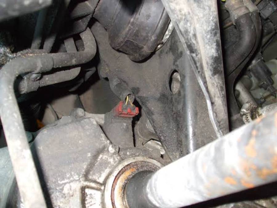
Where Is the P0500 Vehicle Speed Sensor A Located?
The P0500 Vehicle Speed Sensor A is commonly located on the transmission or transaxle, although the exact location depends on how the vehicle measures and reports road speed. On vehicles equipped with a dedicated Vehicle Speed Sensor (VSS), the sensor is typically installed in the transmission housing where it can monitor the rotation of an output component associated with vehicle speed. The sensor then generates a signal that the vehicle’s control system uses to determine how fast the vehicle is moving.
The location varies because manufacturers do not use one universal speed-sensing architecture. A front-wheel-drive vehicle may have the sensor mounted on the transaxle, while another drivetrain may position a speed sensor around the transmission output area. Other vehicles derive vehicle-speed information from wheel speed sensors and the ABS system rather than relying on a traditional standalone VSS. Therefore, a generic diagram showing a sensor on a transmission should not be treated as the correct P0500 Vehicle Speed Sensor A location for every vehicle.
Where Is Vehicle Speed Sensor A Located on the Transmission?
A transmission-mounted Vehicle Speed Sensor A is generally installed in or on the transmission housing near a component whose rotational speed corresponds to vehicle movement. Depending on the transmission design, this may place the sensor around the output section of the transmission or transaxle. An electrical connector and wiring harness attached to the sensor provide useful visual references when locating it.
Do not identify the sensor by location alone. Modern transmissions can contain multiple speed-related sensors, including input speed and output speed sensors, and these components can look similar from outside the transmission. The correct component should be identified using the service information, wiring diagram, or component-location diagram for the exact year, make, model, engine, and transmission.
Can Vehicle Speed Sensor A Be a Wheel Speed Sensor?
Vehicle speed information can come from wheel speed sensors on vehicles that calculate road speed through the ABS system, but a wheel speed sensor should not automatically be identified as Vehicle Speed Sensor A. Wheel speed sensors measure individual wheel rotation and send that information to the ABS control system. Depending on the vehicle architecture, processed speed information can then be shared with other control modules that require vehicle-speed data.
This distinction matters when diagnosing P0500. Replacing a transmission-mounted sensor simply because a generic P0500 description mentions a Vehicle Speed Sensor can fail to correct the problem if that particular vehicle obtains its road-speed information through another system. The same applies to replacing an ABS wheel speed sensor without determining which speed signal the PCM or ECM actually monitors for P0500.
How Can You Find Vehicle Speed Sensor A on Your Specific Vehicle?
Find the correct Vehicle Speed Sensor A by matching the P0500 code to the component and wiring information for the vehicle’s exact configuration. Five vehicle details are particularly important: model year, make, model, engine, and transmission or drivetrain configuration. Two vehicles carrying the same model name can use different transmissions or speed-sensing systems, so model information alone may not identify the correct sensor.
Start by checking the manufacturer’s component-location information or an appropriate repair manual for the exact vehicle. Locate the Vehicle Speed Sensor, speed sensor “A,” or the speed-signal component specified by the manufacturer. Then compare its connector, wiring route, mounting position, and surrounding components with the sensor on the vehicle. This approach is more reliable than identifying a sensor from appearance alone.
The wiring diagram provides another way to confirm the component. Trace the vehicle-speed signal from its source toward the PCM, ECM, TCM, ABS module, or other relevant controller. This shows whether the vehicle uses a dedicated VSS, a transmission speed sensor, or speed information generated elsewhere in the vehicle network. It also helps distinguish a sensor problem from an open circuit, damaged connector, or other signal-path fault.
Confirm the sensor designation before disconnecting or replacing anything. A P0500 code identifies a problem involving vehicle-speed information; it does not, by itself, prove that a particular physical sensor has failed. Correct identification of the speed-sensing architecture is therefore the first diagnostic step after retrieving the code.
Is Vehicle Speed Sensor A the Same as the Transmission Output Speed Sensor?
Vehicle Speed Sensor A and the transmission output speed sensor are not universally the same component. The names can refer to closely related functions on certain vehicles, but manufacturer terminology and control-system design determine how each sensor is identified and used. A generic parts description should therefore not override the terminology in the vehicle-specific service information.
A transmission output speed sensor measures the rotational speed of a transmission output component. The control system can use this information for transmission operation and, depending on the design, may also use or process it when determining vehicle speed. A traditional VSS similarly provides information related to road speed, which explains why the terms are sometimes confused when diagnosing P0500.
The practical distinction is the circuit monitored by the vehicle. If the manufacturer identifies a specific output speed sensor as the source of the vehicle-speed signal associated with P0500, that component becomes relevant to diagnosis. If vehicle speed comes from another sensor or control module, replacing an output speed sensor simply because it is mounted near the transmission output will not address the actual fault.
Use the vehicle-specific wiring diagram and diagnostic procedure to establish the relationship between the sensor and P0500. This prevents confusion between input speed sensors, output speed sensors, dedicated Vehicle Speed Sensors, and ABS-derived vehicle-speed signals, all of which can involve rotational-speed data but perform different roles depending on the vehicle.
Is Vehicle Speed Sensor A the Same as an ABS Wheel Speed Sensor?
Vehicle Speed Sensor A is not automatically the same component as an ABS wheel speed sensor. A dedicated Vehicle Speed Sensor measures rotational speed at a drivetrain component, while an ABS wheel speed sensor measures the rotational speed of an individual wheel. However, some vehicle architectures use wheel-speed information from the ABS system to determine vehicle speed, which creates confusion when diagnosing P0500.
ABS-equipped vehicles generally have a wheel speed sensor associated with each monitored wheel. These sensors provide wheel-rotation information that the ABS control module uses to detect differences in wheel speed during braking and other operating conditions. Depending on the vehicle design, vehicle-speed information derived from these signals can also be shared with the PCM, ECM, TCM, instrument cluster, or other modules that require road-speed data.
The diagnostic difference is important because P0500 does not identify an ABS wheel speed sensor as faulty simply because the vehicle uses wheel-speed information. A technician or DIY owner must determine where the PCM or ECM receives the vehicle-speed signal and which circuit is monitored for the code. For example, an individual wheel speed sensor fault may produce an ABS-related trouble code on one vehicle, while a problem in the vehicle-speed data path can contribute to P0500 on another architecture.
Check the vehicle-specific wiring diagram and diagnostic information before replacing an ABS sensor. If scan data shows one wheel reporting a significantly different speed from the other wheels, that information provides a diagnostic direction, but the sensor, wiring, connector, tone ring, and signal path still need to be checked before a component is condemned.
What Does the P0500 Code Mean?
P0500 means the vehicle’s powertrain control system has detected a malfunction involving the vehicle-speed signal. The code is commonly described as “Vehicle Speed Sensor A Malfunction,” but that description does not establish that the physical speed sensor itself has failed.
The vehicle-speed signal allows control modules to determine whether the vehicle is stationary or moving and how quickly it is traveling. Depending on the vehicle, this information can originate from a dedicated VSS, a transmission-related speed sensor, or speed data processed through another control system. The PCM or ECM compares this information with the operating conditions it expects to see. A missing, implausible, or otherwise incorrect speed signal can result in P0500 when the applicable diagnostic conditions are met.
This distinction explains why locating Vehicle Speed Sensor A is only one part of P0500 diagnosis. The fault can exist at the sensor, its electrical circuit, the component used to generate the speed signal, or another part of the speed-data path. The exact diagnostic criteria vary by manufacturer, so vehicle-specific service information should determine which circuit and components need to be tested.
P0500 should therefore be treated as a vehicle-speed signal fault rather than immediate proof of a failed sensor. Reading additional powertrain, transmission, and ABS trouble codes can provide important context before any parts are replaced.
What Symptoms Can Appear With a P0500 Code?
P0500 can cause an inaccurate or non-working speedometer, abnormal transmission shifting, a Check Engine Light, and problems with systems that depend on vehicle-speed information. The exact symptoms depend on which component has failed and how the vehicle distributes speed data between its control modules.
An inaccurate speedometer is one of the most directly related symptoms. If the instrument cluster depends on the affected speed signal, the displayed speed may remain at zero, fluctuate, or disagree with the vehicle’s actual road speed. However, a normal speedometer does not automatically rule out P0500 because the instrument cluster and PCM do not use the same speed-data pathway on every vehicle.
Automatic transmission operation can also change when valid vehicle-speed information is unavailable. Transmission control strategies use rotational and vehicle-speed data when determining operating conditions and shift behavior. An incorrect signal can therefore be associated with delayed, irregular, or otherwise abnormal shifting on vehicles where the affected speed information is part of the transmission-control strategy.
Warning lights provide another diagnostic clue. The Check Engine Light can illuminate when P0500 is stored, while ABS or traction-control warnings may also appear when the underlying problem involves speed information shared with those systems. Multiple warning lights do not prove that multiple components have failed; they can result when several control systems depend on related speed data.
Cruise control and other speed-dependent functions may also stop operating correctly. These systems require reliable vehicle-speed information to maintain or adjust their operation. The combination of P0500 with a faulty speedometer, abnormal shifting, or related warning lights helps identify which part of the vehicle-speed system should be investigated first.
What Causes a P0500 Code Besides a Bad Vehicle Speed Sensor?
P0500 can result from faults in the speed-signal circuit or related speed-sensing system even when Vehicle Speed Sensor A itself is working correctly. The relevant causes include damaged wiring, loose or corroded electrical connections, problems with the mechanism that generates the speed signal, and faults elsewhere in the vehicle-speed data path. The applicable causes depend on the speed-sensing architecture used by the vehicle.
Damaged wiring is an important cause because the sensor must transmit an electrical signal to the relevant control system. Wiring can develop an open circuit, short circuit, damaged insulation, poor terminal contact, or other connection problem. A sensor producing the correct signal cannot provide useful speed information to the control module if that signal is lost before reaching its destination.
Connector problems can produce a similar result. Moisture, corrosion, loose terminals, damaged connector locks, and poor pin contact can interrupt or distort the signal. Inspecting the connector and harness is therefore necessary before replacing a sensor, particularly when the wiring is routed near the transmission, suspension, wheel hub, or other areas exposed to heat, movement, water, and road debris.
The component that allows the sensor to detect rotation can also be involved. Depending on the design, a speed sensor works with a rotating target such as a reluctor or tone ring. Damage, excessive contamination, incorrect clearance, or mechanical problems affecting that target can prevent the sensor from producing the expected signal even when its electrical components remain functional.
Vehicles that derive road speed from ABS wheel-speed information introduce additional possible failure points. A wheel speed sensor, its wiring, the associated tone ring, ABS-related speed processing, or the communication path carrying vehicle-speed data may need to be investigated according to the vehicle-specific diagnostic procedure.
For this reason, replacing Vehicle Speed Sensor A should follow diagnosis rather than precede it. P0500 identifies the affected function—the vehicle-speed signal—but the code alone does not identify which physical component caused that signal to become invalid.
How Do You Diagnose a P0500 Code After Finding the Sensor?
Diagnose P0500 by checking the stored trouble codes, inspecting the speed sensor and its circuit, examining live speed data, testing the signal when required, and verifying the repair with a road test. Finding Vehicle Speed Sensor A does not establish that the sensor is defective. Diagnosis should determine where the vehicle-speed information becomes incorrect before any component is replaced.
Start by scanning all relevant control modules rather than reading only the P0500 code from the engine controller. Record P0500 and any additional transmission, ABS, wheel-speed, or communication codes. Related codes can help determine whether the problem originates at a dedicated Vehicle Speed Sensor, a transmission speed sensor, an ABS wheel speed sensor, or another part of the vehicle-speed signal path.
Inspect the sensor and surrounding components next. Check the electrical connector for loose terminals, corrosion, moisture, damaged pins, or a broken locking tab. Follow the accessible wiring harness and look for cuts, melted insulation, rubbing, stretched wiring, or previous repairs. If the sensor reads a reluctor or tone ring, inspect the accessible signal-generating components for damage or contamination where the vehicle design permits.
Use scan-tool live data to determine whether the control module receives a plausible speed signal while the vehicle is moving. A vehicle-speed value that remains at zero, drops out intermittently, or changes abnormally provides a direction for further testing. On vehicles using ABS-derived speed information, comparing individual wheel-speed readings can help isolate an abnormal signal. Interpret those readings according to the specific vehicle architecture rather than assuming one universal data pattern.
Electrical testing should follow the manufacturer’s procedure for the specific sensor. Vehicle speed sensors can use different electrical designs, so there is no single resistance, voltage, or waveform specification that applies to every VSS. Verify the sensor’s power supply, ground, signal circuit, continuity, or output waveform according to the applicable wiring diagram and service specifications.
What Should You Inspect Before Replacing Vehicle Speed Sensor A?
Inspect the connector, wiring harness, sensor mounting area, and speed-signal target before replacing Vehicle Speed Sensor A. These components can create the same loss or corruption of vehicle-speed information that a failed sensor produces.
Pay particular attention to wiring located near moving or hot components. Transmission wiring can be exposed to heat, fluid contamination, vibration, and physical contact, while wheel-speed wiring is exposed to suspension movement, water, dirt, and road debris. A damaged conductor or poor terminal connection can produce an intermittent P0500 even when the sensor continues to operate.
Check the sensor mounting condition as well. A loose sensor, damaged mounting point, contamination, or an abnormal relationship between the sensor and its rotating target can interfere with signal generation. The exact inspection procedure depends on the sensor design, so avoid applying a generic clearance or resistance specification to every vehicle.
How Can You Test Vehicle Speed Sensor A?
Test Vehicle Speed Sensor A according to its circuit design and the manufacturer’s specifications rather than using one universal multimeter value. The required test can involve checking power and ground, measuring the signal, checking circuit continuity, monitoring scan-tool data, or observing the sensor waveform with suitable diagnostic equipment.
Begin with the wiring diagram to identify the terminals and determine what type of signal should be present. Test the circuit under the conditions specified by the manufacturer. If the sensor receives the correct electrical supply and ground but does not produce the required output while its target rotates correctly, the sensor becomes a stronger suspect. If the expected signal leaves the sensor but does not reach the receiving control module, investigate the circuit between those points instead.
After completing the repair, clear the diagnostic codes and operate the vehicle under appropriate conditions. Confirm that vehicle-speed data responds normally, P0500 does not return, and affected functions such as the speedometer or transmission operation have returned to normal. This final verification prevents an intermittent or secondary fault from being mistaken for a completed repair.
Can You Drive With a P0500 Code?
A vehicle with P0500 may still move, but it should not be assumed to operate normally or safely until the vehicle-speed fault is diagnosed. The practical risk depends on which speed signal has been lost and which vehicle systems rely on that information.
A malfunctioning speedometer creates an obvious driving concern because the driver may not have reliable information about road speed. Transmission behavior can also be affected on vehicles that use the faulty speed information as part of their shift strategy. ABS, traction-control, cruise-control, or other speed-dependent functions may also become unavailable or operate differently when the required speed data is missing.
Warning lights and vehicle behavior should guide the immediate response. Avoid continued driving when the vehicle shifts abnormally, the speedometer cannot provide usable information, multiple safety-system warnings appear, or the vehicle exhibits behavior that makes normal operation uncertain. The purpose of retrieving P0500 is not simply to clear the Check Engine Light but to restore reliable vehicle-speed information to the systems that require it.
How Much Does It Cost to Replace Vehicle Speed Sensor A?
The cost to replace Vehicle Speed Sensor A depends on the vehicle, sensor location, component design, labor access, and whether the sensor is actually responsible for P0500. A universal replacement price would be misleading because a readily accessible external transmission sensor requires a different repair process from a fault involving wheel-speed hardware, wiring, or another part of the speed-signal system.
The repair bill can contain three separate costs: diagnosis, replacement parts, and labor. Diagnostic time becomes particularly important when P0500 is intermittent or when several control modules participate in generating and distributing vehicle-speed information. In these cases, replacing the first speed sensor found on the vehicle can increase the total repair cost without correcting the original fault.
Sensor accessibility also affects labor. An externally mounted sensor with an accessible connector can require relatively little disassembly, while components positioned behind other parts require additional labor. Wiring damage can require circuit tracing and repair instead of sensor replacement. Vehicle-specific parts and labor information is therefore necessary before estimating the actual repair cost.
Read more: Hyundai P0455: Meaning, Causes, Symptoms, Diagnosis, and Fix
Can Replacing Vehicle Speed Sensor A Fix P0500?
Replacing Vehicle Speed Sensor A can fix P0500 when testing confirms that the sensor is responsible for the incorrect or missing vehicle-speed signal. Replacement is not a guaranteed solution because P0500 identifies a malfunction involving vehicle-speed information rather than proving that one specific sensor has failed.
A confirmed sensor failure provides a clear repair path. For example, the sensor becomes a valid replacement candidate when its power supply, ground, wiring, connector, and signal-generating target meet the applicable specifications but the sensor fails to produce the required output. The replacement should then be followed by code clearing, live-data verification, and a road test.
Replacing the sensor is unlikely to solve P0500 when the actual problem is an open or shorted circuit, damaged connector, defective reluctor or tone ring, incorrect wheel-speed information, or another fault in the vehicle-speed data path. Those faults must be repaired at their source.
The correct repair sequence is therefore locate the speed-signal source, identify the correct component, inspect the circuit, test the signal, repair the confirmed fault, and verify vehicle-speed data afterward. This process prevents unnecessary parts replacement and addresses the reason P0500 was stored rather than treating the trouble-code description as a parts-replacement instruction.