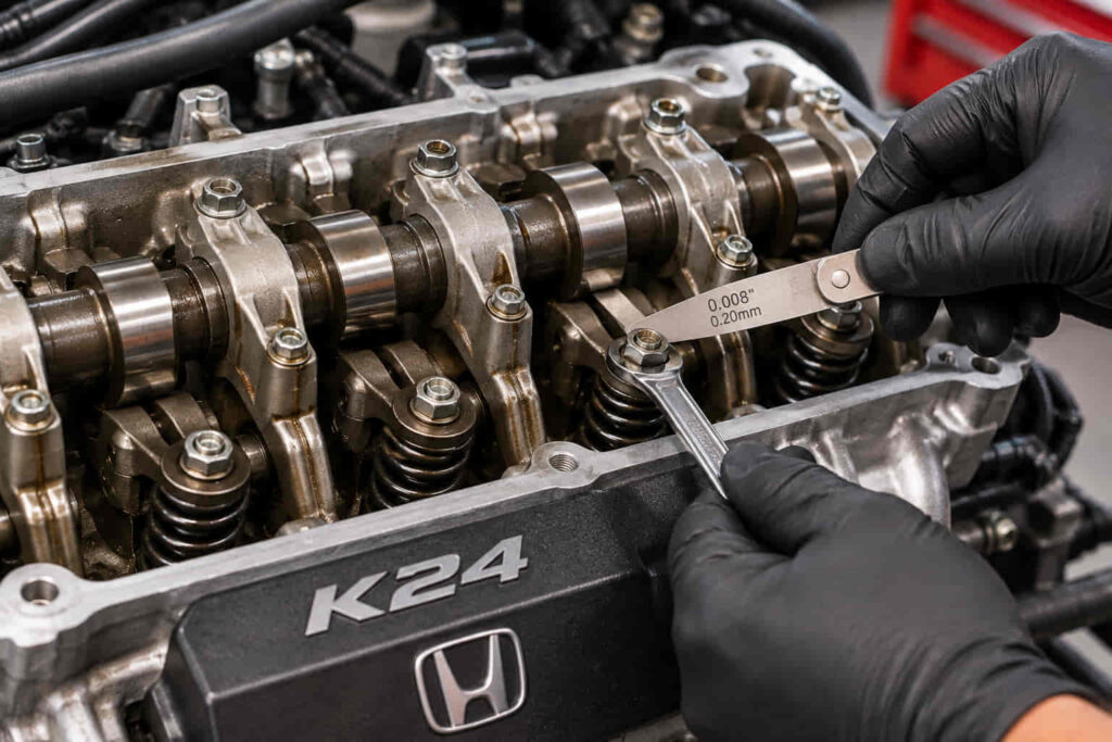
K24 valve adjustment is the process of measuring and correcting the clearance between the valve stem and rocker arm adjusting screw on Honda’s 2.4-liter K-series engine. Proper valve clearance allows the intake and exhaust valves to open and close correctly as engine components expand with temperature. Most Honda K24 engines require the adjustment to be performed with a cold cylinder head using a feeler gauge, an adjusting screwdriver, and a locknut wrench.
For many Honda K24 engines, the specified cold intake valve clearance is 0.21–0.25 mm (0.008–0.010 inches). However, exhaust valve clearance differs between engine variants. The K24A4 used in the 2003 Honda Accord specifies 0.28–0.32 mm (0.011–0.013 inches) for the exhaust valves, while the K24A2 found in the 2004 Acura TSX specifies 0.25–0.29 mm (0.010–0.011 inches).
Later engines such as the K24Z7 in the Civic Si also use the 0.25–0.29 mm exhaust range. This difference makes identifying the exact K24 engine code essential before adjusting the valves.
Honda K24 engines use a mechanical valve lash adjustment system rather than relying on conventional hydraulic lash adjusters to automatically eliminate clearance. Over time, valve seat wear, component wear, and thermal cycling can change the clearance. Excessive clearance may produce ticking noises, while insufficient clearance can prevent valves from seating correctly and contribute to compression loss or burned exhaust valves.
A properly performed K24 valve adjustment can restore correct valvetrain operation, reduce abnormal noise, and help maintain engine performance. However, the procedure requires accurate measurements, correct cylinder positioning, and the appropriate specifications for the engine.
What Is K24 Valve Adjustment?
K24 valve adjustment involves setting the clearance between each valve stem and its rocker arm adjusting screw while the corresponding camshaft lobes are positioned away from the valve-opening portion of their operating cycle.
The Honda K24 is a 2.4-liter inline-four engine belonging to Honda’s K-series engine family. It uses a dual-overhead-camshaft architecture and a timing chain to coordinate crankshaft and camshaft rotation.
Depending on the version, the engine incorporates Honda’s i-VTEC variable valve timing and lift technology.
The cylinder head contains 16 valves, with four valves per cylinder. Each cylinder has two intake valves and two exhaust valves.
The intake valves control airflow entering the combustion chamber, while the exhaust valves allow combustion gases to leave the cylinder.
Valve operation is controlled through the camshafts and rocker arms.
As the camshaft rotates, its lobes cause the rocker arms to open and close the valves according to the engine’s timing requirements.
The mechanical adjustment system includes an adjusting screw and locknut.
The clearance between the screw and valve stem must remain within a specified range when the valve is closed.
This gap is necessary because the cylinder head, valves, and other components expand as engine temperature increases.
A valve that has insufficient cold clearance may be held slightly open after the engine becomes hot.
Excessive clearance can create noise and alter the effective valve-opening motion.
K24 valve adjustment restores the specified mechanical relationship between the rocker arm and valve stem.
The adjustment is performed individually for all intake and exhaust valves.
Because the engine uses two intake and two exhaust valves per cylinder, the complete procedure requires checking 16 valve clearances.
What Are the Correct K24 Valve Clearance Specs?
The correct K24 valve clearance depends on the engine variant. Many versions specify 0.21–0.25 mm for the intake valves, while the exhaust specification may be either 0.25–0.29 mm or 0.28–0.32 mm.
For the 2003 Honda Accord 2.4L engine, the service manual specifies an intake clearance of 0.21–0.25 mm, equivalent to approximately 0.008–0.010 inches.
The exhaust clearance is 0.28–0.32 mm, equivalent to approximately 0.011–0.013 inches.
The 2004 Acura TSX with the K24A2 uses the same intake clearance of 0.21–0.25 mm.
However, its exhaust valves require 0.25–0.29 mm, approximately 0.010–0.011 inches.
The Honda CR-V K24Z1 service information specifies 0.21–0.25 mm for the intake and 0.28–0.32 mm for the exhaust.
The K24Z7 in the 2012–2015 Civic Si uses 0.21–0.25 mm for the intake and 0.25–0.29 mm for the exhaust.
Service information for the 2015 Accord 2.4L also specifies the 0.21–0.25 mm intake range and 0.25–0.29 mm exhaust range.
These differences are important because the K24 designation refers to an engine family rather than one unchanging mechanical configuration.
Honda developed multiple cylinder head, camshaft, and valvetrain arrangements throughout the K24 production history.
The valve clearance specification must therefore correspond to the exact engine code and application.
Using an exhaust setting of 0.30 mm on an engine that specifies a maximum of 0.29 mm would place that clearance outside its published range.
Similarly, setting the exhaust valves to 0.26 mm on an engine requiring a minimum of 0.28 mm would make them too tight.
Before beginning the adjustment, verify the engine code, model year, and factory service specifications.
K24A2 Valve Adjustment Specs
The Honda K24A2, used in the first-generation Acura TSX, specifies a cold intake valve clearance of 0.21–0.25 mm and an exhaust clearance of 0.25–0.29 mm.
The K24A2 is a performance-oriented version of Honda’s K24 engine family.
It uses a dual-overhead-camshaft cylinder head and i-VTEC technology designed to provide strong performance over a broad engine speed range.
The engine’s rocker arm arrangement allows mechanical valve lash adjustment without replacing the entire camshaft or cylinder head.
The 2004 Acura TSX service procedure specifies that valve adjustment should be performed only when the cylinder head temperature is below 100°F, equivalent to 38°C.
The procedure begins with cylinder number one positioned at top dead center on its compression stroke.
The technician then measures the clearance between each adjusting screw and valve stem.
If the clearance falls outside the specified range, the adjuster is repositioned and the locknut is tightened.
The 2004 TSX service information specifies a locknut torque of 20 Nm, approximately 14 lb-ft.
The clearance must be checked again after tightening the locknut.
This recheck is essential because the adjusting screw can move slightly as the nut is secured.
A performance-oriented K24A2 may also be equipped with aftermarket camshafts, valve springs, or modified cylinder head components.
When aftermarket components are installed, the original Honda specifications may no longer apply.
The camshaft or valvetrain manufacturer should provide the appropriate lash recommendations.
For a stock K24A2, however, the factory cold clearance ranges remain the correct starting point.
K24A4 and K24A1 Valve Adjustment
Several early K24 engines use the wider 0.28–0.32 mm exhaust clearance range, but their individual service manuals should be checked before adjustment.
The K24A4 was used in early 2000s Honda Accord models.
Its published 2003 Accord service specifications identify 0.21–0.25 mm for the intake valves and 0.28–0.32 mm for the exhaust valves.
The procedure also distinguishes between intake and exhaust locknut torque.
The intake adjusting locknuts require 20 Nm, approximately 14 lb-ft.
The exhaust adjusting locknuts require 14 Nm, approximately 10 lb-ft.
Honda specifies applying engine oil to the locknut threads during the procedure.
These details matter because the locknut torque is not necessarily identical across both sides of the cylinder head.
The K24A1 was used in early Honda CR-V applications and belongs to the same broad K24 development period.
However, engine code and model-specific instructions should be verified rather than assuming every early K24 uses exactly the same dimensions and fasteners.
The K24A family contains different cylinder head configurations and operating characteristics.
Some versions were developed primarily for everyday efficiency and low-speed torque.
Others were intended for higher-output applications.
Their camshafts, rocker systems, and related components can differ.
For a stock Accord or CR-V engine, the appropriate Honda factory specification should determine the final adjustment.
For an engine swap using mixed K24 components, the actual installed cylinder head and valvetrain are especially important.
A K24A4 block fitted with a different K-series cylinder head may no longer follow the original K24A4 valve clearance specifications.
K24Z7 Valve Adjustment Specs
The K24Z7 engine used in the 2012–2015 Honda Civic Si specifies 0.21–0.25 mm intake clearance and 0.25–0.29 mm exhaust clearance when adjusted cold.
The K24Z7 is a 2.4-liter performance engine developed for the ninth-generation Civic Si.
Its cylinder head and valvetrain differ from certain earlier K24 configurations.
The service procedure specifies that the engine coolant temperature should be below 100°F, or 38°C, before measuring valve clearance.
Honda recommends checking the temperature through its diagnostic system when necessary.
The engine must be positioned at top dead center for cylinder number one before the initial measurements.
The VTC actuator and exhaust camshaft sprocket have timing marks that help establish the correct position.
The technician measures the valve clearance using a feeler gauge inserted between the adjusting screw and valve stem.
The gauge should move with slight resistance.
If the gap is incorrect, the locknut is loosened and the adjuster is turned until the required clearance is achieved.
For the K24Z7, the published adjusting locknut torque is 14 Nm, approximately 10 lb-ft, for the specified 7 × 0.75 mm locknut.
Honda specifies applying new engine oil to the locknut threads.
After the nut is tightened, the clearance is checked again.
The crankshaft is then rotated 180 degrees clockwise to position the next cylinder.
The sequence continues through cylinders three, four, and two.
This procedure is important for Civic Si owners because applying the wider exhaust clearance used in certain Accord and CR-V engines could result in an incorrect K24Z7 setting.
K24W Valve Adjustment Specs
The K24W-series engine used in later Honda Accord models has a different cylinder head and fuel injection design from earlier K24A engines, and its valve clearance should be set using the corresponding model-year service information.
The K24W family introduced important changes to Honda’s 2.4-liter engine architecture.
These included revised cylinder head packaging and direct fuel injection in relevant applications.
The engine’s mechanical arrangement differs from earlier port-injected K24A designs.
For the 2015 Honda Accord 2.4L, the service procedure specifies an intake clearance of 0.21–0.25 mm and an exhaust clearance of 0.25–0.29 mm.
The procedure begins with the engine positioned at cylinder number one top dead center.
The technician identifies the appropriate VTC and exhaust camshaft timing marks before checking the rocker arm adjusting screws.
The clearance is measured between the adjusting screw and valve stem.
The locknut is then secured using the torque specified for the engine.
These details demonstrate why the name K24 alone is not sufficient to identify the correct specifications.
A 2003 Accord K24A4 and a 2015 Accord K24W both have approximately 2.4 liters of displacement, but their exhaust valve clearance requirements differ.
The engine’s actual design and service instructions must determine the setting.
For replacement cylinder heads or engine swaps, the installed valvetrain should also be identified.
The correct procedure is based on the physical engine components rather than the vehicle badge alone.
Why Do Honda K24 Engines Need Valve Adjustment?
Honda K24 engines need periodic valve clearance inspection because their mechanical valvetrain components can experience changes in clearance as the engine accumulates operating hours and mileage.
The valve clearance gap is deliberately incorporated into the engine design.
When the engine is cold, the clearance allows for expansion of the valves and other components as operating temperature increases.
The intake valves and exhaust valves are exposed to different thermal conditions.
Exhaust valves operate in a particularly demanding environment because they are exposed to hot combustion gases leaving the cylinders.
The valve also transfers heat through its seat and guide into the cylinder head.
Over time, wear can occur at the valve seat and valve face.
As the valve sits deeper in its seat, the valve stem may effectively move closer to the adjusting screw.
This can reduce valve clearance.
Other types of valvetrain wear can increase clearance.
The resulting direction of change depends on the components involved.
An engine with excessive clearance may develop audible ticking.
An engine with insufficient clearance may run quietly while experiencing poor valve seating.
Because the symptoms are not always obvious, a mechanical inspection provides more reliable information than listening alone.
Honda’s Maintenance Minder system includes valve clearance inspection as part of its service recommendations.
The purpose is to verify that the valvetrain continues operating within its designed clearance range.
Correct adjustment supports combustion sealing, valve timing accuracy, and reliable long-term operation.
How Often Should You Adjust K24 Valves?
K24 valve adjustment intervals depend on the vehicle’s model year and maintenance schedule, but Honda commonly includes valve clearance inspection under Maintenance Minder service code 4.
Honda’s Maintenance Minder system calculates maintenance requirements using vehicle operating conditions and service history.
Code 4 commonly includes spark plug replacement and valve clearance inspection.
For certain vehicles, additional maintenance tasks may apply according to the engine configuration.
Honda also advises adjusting valves when they become noisy during relevant service visits.
However, valve noise is not the only reason to investigate clearance.
Tight exhaust valves can become quieter rather than louder.
For this reason, an engine with high mileage and no documented valve clearance inspection may benefit from checking the clearances even when it does not produce obvious ticking.
Some Acura materials refer to a major engine service around 100,000 miles.
However, this should not be treated as a universal fixed interval for every K24.
The actual service timing depends on the maintenance schedule for the specific vehicle.
An engine that has received cylinder head repairs or aftermarket camshaft modifications may also require inspection at a different interval.
For a normal street vehicle, follow the applicable Honda or Acura maintenance schedule.
If the engine has unusual valve noise, misfires, rough idle, or unexplained compression problems, a valve clearance inspection may be appropriate before the next scheduled service.
What Are the Symptoms of Incorrect K24 Valve Clearance?
Incorrect K24 valve clearance can cause ticking noises, rough idle, reduced performance, abnormal combustion behavior, or compression loss depending on whether the gap is too loose or too tight.
Excessive clearance is commonly associated with an audible tapping or ticking sound.
The noise originates from the additional gap that must be taken up as the rocker arm begins opening the valve.
The sound may be particularly noticeable during cold operation.
However, not every tapping noise indicates incorrect valve lash.
Fuel injector operation, timing chain components, exhaust leaks, and other engine systems can produce similar sounds.
Insufficient clearance can be more difficult to identify.
A tight valve may not fully close when the engine reaches operating temperature.
This can reduce cylinder compression and affect combustion.
The engine may develop a rough idle, misfire, or reduced power.
In some cases, the problem becomes more noticeable when the engine is hot.
A valve that cannot fully seat may also lose an important path for transferring heat into the cylinder head.
Over time, this can contribute to exhaust valve damage.
However, the presence of a misfire does not prove that valve clearance is incorrect.
Ignition coils, spark plugs, fuel injectors, and other components may produce similar symptoms.
The appropriate diagnostic approach combines valve clearance measurement with other testing when necessary.
Read more: LS Engine Torque Specs
What Tools Are Needed for K24 Valve Adjustment?
A K24 valve adjustment requires a suitable feeler gauge set, an adjusting screwdriver, a locknut wrench, a torque wrench, and tools for removing the cylinder head cover and rotating the crankshaft.
The feeler gauge is the most important measuring tool.
It consists of thin metal blades manufactured to specific thicknesses.
These blades are inserted into the clearance between the rocker arm adjusting screw and the valve stem.
A gauge set should contain sizes that match the engine’s specified intake and exhaust ranges.
Metric gauges are useful because Honda publishes valve clearance specifications in millimeters.
For example, a 0.23 mm gauge can be used as a practical reference near the center of the common intake clearance range.
A 0.27 mm gauge is within the 0.25–0.29 mm exhaust range.
A 0.30 mm gauge is within the 0.28–0.32 mm exhaust range.
However, selecting the gauge thickness must follow the correct engine specification.
A flat-head screwdriver is used to turn the adjusting screw.
A suitable locknut wrench allows the locknut to be tightened while the adjusting screw remains in position.
Honda identifies specialized tappet adjusting tools for certain K24 applications.
A small torque wrench is necessary because the locknut torque can differ by engine.
Additional tools may include sockets, ratchets, extensions, and equipment for safely rotating the crankshaft.
The cylinder head cover gasket and spark plug tube seals should also be inspected.
Replacement sealing components may be necessary if the existing parts are damaged or deteriorated.
The appropriate service manual should be available during the procedure.
Should K24 Valve Adjustment Be Done Cold or Hot?
K24 valve clearance should be measured and adjusted with the cylinder head cold, generally below 100°F (38°C), according to the relevant Honda service procedures.
This temperature requirement is important because engine components expand as they heat up.
The valve stem, cylinder head, camshaft support structure, and related components do not necessarily expand by identical amounts.
As a result, the clearance measured with a hot engine may differ from the clearance measured when cold.
The published valve lash specifications assume the engine is within the specified temperature range.
Adjusting a hot engine using cold clearance values can produce an incorrect setting after the engine cools.
In normal workshop conditions, allowing the vehicle to sit overnight often provides a suitable starting point.
However, ambient temperature and engine operating history affect cooling time.
An engine that was operated recently may remain above the service limit even when the outside of the valve cover feels relatively cool.
Some Honda service procedures recommend monitoring coolant temperature with the Honda Diagnostic System.
For the K24Z7, the manual specifically identifies an engine coolant temperature below 38°C.
If there is uncertainty about engine temperature, measuring it is preferable to estimating by touch.
The engine should also be switched off during the procedure.
The crankshaft is rotated manually to position the cylinders.
Correct temperature control improves measurement consistency and reduces the chance of an incorrect adjustment.
How to Prepare the K24 Engine for Valve Adjustment
Preparing the K24 engine involves allowing it to cool, gaining access to the cylinder head, identifying the correct engine specifications, and ensuring the crankshaft can be rotated safely.
The vehicle should be parked securely on a level surface.
The engine must be off and cool enough to meet the service temperature requirement.
Before removing components, verify the engine code and the applicable valve clearance specifications.
Any engine covers, ignition coil covers, or surrounding components obstructing access must be removed according to the vehicle’s service instructions.
The ignition coils may need to be disconnected and removed.
Depending on the vehicle, access may also require removing the windshield cowl or other nearby components.
The cylinder head cover can then be removed.
Care should be taken not to damage the gasket or sealing surfaces.
The exposed valvetrain should be visually inspected for abnormal wear, sludge accumulation, damaged components, or other problems.
If significant damage is visible, simply adjusting valve clearance may not be sufficient.
The crankshaft must be rotated to position each cylinder correctly.
Honda’s service procedures generally specify clockwise crankshaft rotation when viewed from the pulley end.
The timing chain, camshafts, and VTC actuator should remain properly synchronized.
There is no reason to remove the timing chain for an ordinary valve clearance adjustment.
However, the timing marks must be identified accurately before measuring the first cylinder.
The engine should not be cranked or started while the valve cover is removed for measurement.
How to Set Cylinder Number One at Top Dead Center
The K24 valve adjustment procedure begins by positioning cylinder number one at top dead center on the compression stroke, with the camshaft timing marks aligned according to Honda’s service instructions.
Top dead center describes the highest position of the piston within its cylinder.
However, a four-stroke engine reaches top dead center twice during each complete operating cycle.
One occurs near the transition between the compression and power strokes.
The other occurs near the transition between the exhaust and intake strokes.
The correct position for valve clearance measurement is top dead center on the compression stroke.
At this position, both intake and exhaust valves should be closed.
The relevant camshaft lobes should not be applying valve-opening lift.
Honda provides timing marks on the variable timing control actuator and exhaust camshaft sprocket.
The service procedure typically identifies punch marks that should point upward.
Additional timing marks are aligned when cylinder number one is in the required position.
These markings provide a more reliable reference than piston position alone.
The engine should be rotated carefully using the crankshaft pulley bolt and an appropriate tool.
Excessive force should not be applied if the engine does not turn normally.
Once the timing marks are aligned, the valve clearances for cylinder number one can be measured.
The technician should confirm that the rocker arms are positioned correctly before inserting a feeler gauge.
Attempting to measure a valve while the camshaft is opening it will produce an invalid reading.
How to Measure K24 Valve Clearance With a Feeler Gauge
K24 valve clearance is measured by inserting the appropriate feeler gauge between the adjusting screw and the end of the valve stem, then evaluating the resistance as the gauge moves through the gap.
The correct measuring point is essential.
The feeler gauge must contact the surfaces specified in the service manual.
For the conventional K24 rocker arm adjustment system, the measurement is taken between the adjusting screw and valve stem.
The gauge should slide through the clearance with slight resistance.
This is commonly described as a light drag.
The gauge should not move completely freely without meaningful contact.
However, it should not require excessive force to insert or remove.
Using a blade that is too thick can create a false impression that the clearance is smaller than it actually is.
For example, a K24 engine with a specified intake range of 0.21–0.25 mm should accept a gauge within that range when the valve is correctly adjusted.
A practical method is to compare the desired gauge with adjacent thicknesses.
The selected target gauge should move with consistent light resistance.
A slightly thicker gauge may fit tightly or fail to pass through the gap.
This helps confirm that the setting is not excessively loose.
However, the gauge should be inserted straight enough to contact the intended surfaces correctly.
An angled gauge can produce an inaccurate measurement.
The technician should repeat the measurement when the reading is uncertain.
Valve clearance is measured individually for each of the 16 valves.
Accurate measurement is more important than completing the job quickly.
How to Adjust the Intake Valves on a K24
K24 intake valve adjustment is performed by loosening the adjuster locknut, turning the adjusting screw until the correct feeler gauge has slight drag, tightening the locknut, and rechecking the clearance.
The engine must be positioned so that the relevant intake valves are fully closed.
For cylinder number one, this means using the appropriate top dead center compression position.
The intake clearance commonly ranges from 0.21 to 0.25 mm.
A target near 0.23 mm is within that range and can provide a practical midpoint for many stock K24 applications.
However, the engine-specific specification remains the controlling requirement.
The locknut is loosened using a suitable wrench.
The adjusting screw can then be rotated using a screwdriver.
Turning the screw changes the gap between the rocker arm adjuster and valve stem.
The correct gauge is inserted while the screw is positioned.
The adjuster is moved carefully until the feeler gauge slides with a slight, consistent drag.
The adjusting screw should then be held in position while the locknut is tightened.
This prevents the screw from turning as the nut is secured.
The required locknut torque depends on the K24 variant.
For the 2003 Accord K24A4, the intake locknut specification is 20 Nm, approximately 14 lb-ft.
For the K24Z7, the published specification is 14 Nm, approximately 10 lb-ft.
After tightening the locknut, remove and reinsert the feeler gauge.
If the drag has changed, repeat the adjustment until the final clearance remains correct after the locknut is secured.
Both intake valves for the cylinder should be checked individually.
How to Adjust the Exhaust Valves on a K24
The K24 exhaust valve adjustment procedure is mechanically similar to the intake procedure, but the exhaust clearance specification and sometimes the locknut torque are different.
The exhaust valves operate under higher thermal loads than the intake valves.
They are exposed directly to hot combustion gases leaving the cylinders.
As a result, the required cold exhaust clearance is generally greater than the intake clearance.
However, the correct exhaust range varies by engine.
For the 2003 Accord K24A4, the exhaust specification is 0.28–0.32 mm.
A target near 0.30 mm is within that range.
For the K24A2 and K24Z7, the exhaust specification is 0.25–0.29 mm.
A target near 0.27 mm is within that range.
These values should not be interchanged.
The technician loosens the exhaust rocker arm adjusting locknut and turns the screw while checking the clearance with the appropriate feeler gauge.
The gauge should move with slight resistance.
Once the setting is correct, the adjusting screw is held in place and the locknut is tightened to the specified torque.
For the 2003 Accord K24A4, the exhaust locknut torque is 14 Nm, approximately 10 lb-ft.
For the 2004 Acura TSX K24A2, the published locknut torque is 20 Nm, approximately 14 lb-ft.
For the K24Z7, the specified torque is 14 Nm.
After tightening, the clearance must be measured again.
Exhaust valve clearance deserves particular attention because insufficient lash can interfere with complete valve seating and increase the risk of heat-related valve damage.
What Is the K24 Firing Order for Valve Adjustment?
The Honda K24 firing order is 1-3-4-2, and the normal valve adjustment procedure follows the same cylinder sequence.
Firing order describes the sequence in which the engine’s cylinders complete their power strokes.
The K24 is an inline-four engine with evenly spaced combustion events.
During two complete crankshaft revolutions, each cylinder completes one full four-stroke operating cycle.
The firing order is cylinder one, followed by cylinder three, cylinder four, and cylinder two.
This sequence provides a convenient way to position each cylinder at top dead center on its compression stroke for valve adjustment.
After checking cylinder number one, the crankshaft is rotated 180 degrees clockwise.
This moves the engine to the next firing position.
Cylinder number three can then be measured and adjusted.
Another 180-degree crankshaft rotation positions cylinder number four.
A final 180-degree rotation positions cylinder number two.
The camshafts rotate at half the crankshaft speed.
Therefore, each 180-degree crankshaft rotation produces approximately 90 degrees of camshaft rotation.
This relationship is reflected in Honda’s service instructions.
Following the correct sequence helps prevent valve clearance measurements from being taken when the camshaft is applying lift.
However, the timing marks and correct compression position should still be confirmed.
Firing order alone is not a substitute for verifying the engine’s mechanical position.
How to Adjust All Four K24 Cylinders in the Correct Sequence
The standard K24 valve adjustment sequence begins with cylinder one at top dead center, then continues through cylinders three, four, and two as the crankshaft is rotated 180 degrees clockwise between cylinders.
With cylinder number one at top dead center on its compression stroke, measure the two intake valves and two exhaust valves.
Any clearances outside the applicable specification are adjusted.
After all four valves have been checked and the final locknut torque verified, the crankshaft is rotated 180 degrees clockwise.
The camshafts rotate approximately 90 degrees during this movement.
Cylinder number three is then positioned for measurement.
Its intake and exhaust valves are checked and adjusted as necessary.
The crankshaft is rotated another 180 degrees clockwise.
Cylinder number four is measured and adjusted.
After the next 180-degree rotation, cylinder number two is positioned for the final group of measurements.
This process covers all 16 valves.
The complete procedure involves three half-turn rotations after the initial cylinder one position.
The technician should keep track of which cylinders have been completed.
However, accurate mechanical positioning is more important than the order in which the adjustment results are recorded.
If the crankshaft is moved past the desired position, the manufacturer’s rotation and timing instructions should be followed to reestablish the correct location.
Once all valves are adjusted, the clearances should be reviewed for consistency.
Any adjusting locknut that moved during tightening must be corrected.
The job is not complete until each final clearance is within the correct engine-specific range.
What Is the Correct K24 Valve Adjustment Locknut Torque?
K24 adjusting locknut torque is not universal. Depending on the engine, published specifications include 20 Nm (14 lb-ft) and 14 Nm (10 lb-ft).
The correct torque depends on the rocker arm and adjusting hardware.
For the 2003 Honda Accord 2.4L, Honda specifies 20 Nm for the intake adjusting locknuts and 14 Nm for the exhaust adjusting locknuts.
The service procedure also specifies applying engine oil to the locknut threads.
For the 2004 Acura TSX K24A2, the published valve adjustment procedure specifies 20 Nm for the adjusting locknut.
For the K24Z7 Civic Si, the specified torque is 14 Nm for the 7 × 0.75 mm locknut, with new engine oil applied to the threads.
These differences demonstrate why a general internet statement that every K24 rocker arm locknut requires the same torque can be incorrect.
The locknut secures the adjusting screw after the clearance has been established.
If the nut is insufficiently tightened, the adjuster may move during operation.
If it is excessively tightened, the threads or surrounding components may be damaged.
The adjusting screw must be held while the nut is tightened.
Afterward, the clearance must be measured again.
It is possible for the clearance to change slightly during final tightening even when the screw appears stationary.
The final measured clearance is what determines whether the adjustment is correct.
Always use the specification associated with the exact cylinder head and rocker arm configuration.
What Happens If K24 Valve Clearance Is Too Tight?
K24 valve clearance that is too tight can prevent a valve from closing completely when the engine reaches operating temperature, potentially causing compression loss, misfires, and exhaust valve damage.
Valve clearance allows the mechanical components to expand without holding the valve open.
When the cold gap is insufficient, thermal expansion may remove the remaining clearance.
The valve may then fail to contact its seat fully.
This can create several problems.
The combustion chamber may lose compression because the valve is not completely sealing.
Reduced compression can affect combustion efficiency and engine smoothness.
The engine may develop a rough idle or misfire.
In more severe cases, hot gases can escape past the valve during combustion.
The exhaust valve is particularly vulnerable because it relies partly on contact with its seat to transfer heat into the cylinder head.
If the valve does not seat correctly, its operating temperature can increase.
Continued operation may damage the valve face or seat.
This is one reason that tight valve clearance can be more serious than the absence of obvious noise suggests.
A tight valve may actually produce less mechanical ticking because the gap has become smaller.
Therefore, listening for valvetrain noise is not a reliable method of confirming that the clearance is correct.
A mechanical inspection with a feeler gauge is necessary.
If the engine already has low compression, a valve adjustment may not restore performance when permanent valve damage has occurred.
Additional diagnosis may be required.
What Happens If K24 Valve Clearance Is Too Loose?
Excessive K24 valve clearance commonly produces valvetrain ticking and can alter the effective valve-opening movement, potentially reducing mechanical efficiency and increasing component wear.
When the gap between the adjusting screw and valve stem is larger than intended, the rocker arm must move farther before it begins opening the valve.
This can create additional impact as the components come into contact.
The result may be an audible tapping or ticking sound.
The noise may become more noticeable during cold startup.
However, the exact sound depends on engine speed, oil temperature, and the amount of excessive clearance.
A very small increase beyond the specification may not produce a clearly audible symptom.
Larger clearance can also reduce the effective time and amount of valve opening.
This may affect cylinder filling and exhaust gas removal.
In severe cases, engine performance can decline.
The repeated mechanical impact can increase stress on the contacting surfaces.
However, a ticking noise does not automatically establish that valve clearance is too loose.
K24 engines have timing chains, camshaft components, fuel injectors, and other mechanisms capable of producing mechanical sounds.
The correct response is to measure the clearance and inspect the relevant components.
Setting the clearance tighter than the manufacturer’s minimum in an effort to eliminate all noise is not appropriate.
The goal is to maintain the specified range, not to eliminate every sound from the operating engine.
Can K24 Valve Adjustment Fix Rough Idle or Misfires?
K24 valve adjustment can correct rough idle or misfires when incorrect valve clearance is the underlying cause, but it cannot repair unrelated ignition, fuel injection, or mechanical problems.
A valve that cannot close completely may reduce cylinder compression.
This can interfere with normal combustion and cause unstable engine operation.
The symptoms may become more noticeable when the engine is warm.
However, rough idle has numerous possible causes.
Spark plugs and ignition coils are common examples.
A defective ignition coil may produce a misfire without any problem involving valve clearance.
Fuel injectors can also affect combustion.
A restricted injector or incorrect fuel delivery may create hesitation, rough idle, or a diagnostic trouble code.
Vacuum leaks and intake system problems can produce similar symptoms.
The engine’s electronic controls may also detect abnormal operating conditions.
For this reason, valve adjustment should be approached as part of accurate diagnosis rather than a guaranteed solution to every misfire.
If compression is low, a cylinder leakage test can help identify whether pressure is escaping through an intake valve, exhaust valve, piston rings, or another location.
Valve clearance measurement can then determine whether insufficient lash is contributing to poor sealing.
If the valve or valve seat has already been damaged, adjusting the rocker arm may not restore proper compression.
In that situation, cylinder head repair may be necessary.
Does K24 Valve Adjustment Affect VTEC Performance?
Correct K24 valve clearance supports normal valvetrain operation, but valve adjustment does not directly change the engine’s VTEC engagement strategy or increase its designed camshaft lift.
Honda’s i-VTEC system combines aspects of variable valve timing and valve lift control, depending on the engine variant.
Different K24 engines use different camshaft and rocker arm arrangements.
Performance-oriented versions such as the K24A2 have different valvetrain characteristics from certain efficiency-focused K24 engines.
The VTEC system changes the operating behavior of the rocker mechanisms under specified conditions.
Valve clearance remains important because the mechanical relationship between the rocker arm and valve stem must stay within the designed range.
Excessive clearance can alter effective valve motion.
Insufficient clearance can interfere with valve seating.
Both conditions may reduce engine performance or create abnormal operating behavior.
However, a valve adjustment does not increase the camshaft’s designed lift or change the electronic conditions that determine VTEC operation.
Problems involving VTEC engagement may also arise from low oil pressure, malfunctioning control solenoids, wiring faults, or other system components.
These problems require their own diagnosis.
For a stock engine, maintaining proper valve clearance helps preserve the intended operating characteristics.
For modified engines, the correct valve lash depends on the installed valvetrain and camshaft specifications.
Should Modified K24 Engines Use Factory Valve Lash Specs?
Modified K24 engines should use the valve clearance specifications appropriate to their installed camshafts, rocker arms, and cylinder head components rather than automatically following the original factory settings.
The factory specifications were developed for specific camshaft profiles and valvetrain arrangements.
An aftermarket camshaft may use different ramp characteristics and operating requirements.
Valve lash can influence the effective beginning and ending of valve opening.
Changing the clearance can therefore affect engine operation.
However, adjusting lash outside the intended range is not an appropriate substitute for selecting the correct camshaft.
An aftermarket camshaft manufacturer may specify a particular cold clearance.
Some performance components are designed to operate with factory-style lash.
Others may require different settings.
The builder must also consider rocker arm compatibility.
A K24 engine swap can combine components from different engine generations.
For example, a K24 short block may be paired with a different K-series cylinder head.
In that situation, the factory specifications associated with the original vehicle may not describe the installed valvetrain.
The actual cylinder head, camshafts, rocker arms, and adjustment hardware determine the appropriate procedure.
Aftermarket valve springs and high-RPM modifications can also increase the importance of proper mechanical inspection.
An engine intended for sustained high-speed operation places greater demands on the valvetrain.
Incorrect clearance may increase stress or reduce performance.
For modified engines, the safest approach is to follow the engine builder’s documented specifications and confirm compatibility with the camshaft manufacturer’s recommendations.
How Much Does K24 Valve Adjustment Cost?
The cost of K24 valve adjustment depends on the vehicle, local labor rates, access to the cylinder head cover, and whether additional gaskets or repairs are required.
The procedure mainly involves labor and precision measurement.
Unlike a timing chain or cylinder head replacement, valve adjustment does not normally require purchasing a large collection of internal engine components.
A qualified technician removes the components obstructing the cylinder head cover.
The crankshaft is then positioned correctly for each cylinder.
All 16 valve clearances are measured and adjusted as necessary.
The engine is reassembled with attention to the cylinder head cover gasket and sealing surfaces.
Labor time varies between models.
An Accord, CR-V, Civic Si, and Acura TSX may provide different levels of access to the valve cover and surrounding components.
Some later vehicles require additional cowl removal or other preliminary work.
The condition of the engine can also affect the job.
A damaged gasket, worn ignition coil connector, or unusual valvetrain condition may require additional parts or diagnostic work.
Prices vary significantly between independent repair shops and dealerships.
For this reason, a fixed nationwide price would not accurately represent every K24 application.
The most useful estimate is a written quote covering valve clearance inspection and adjustment, gasket replacement if required, and reassembly.
When comparing quotations, confirm that the shop intends to measure and adjust all 16 valves rather than simply inspect for noise.
A properly performed service includes verifying the final clearances after the locknuts are tightened.
Can You Perform K24 Valve Adjustment at Home?
K24 valve adjustment can be performed by an experienced DIY mechanic with the correct tools and service information, but it requires precise measurement and careful attention to valve timing and locknut torque.
The procedure does not normally require removing the cylinder head or disassembling the lower engine.
However, it is more demanding than a basic oil or filter change.
The technician must understand how to position each cylinder at top dead center on the compression stroke.
Incorrect cylinder positioning can produce invalid measurements.
The feeler gauge technique also requires consistency.
A gauge that slides with no resistance may indicate excessive clearance.
A gauge that must be forced between the surfaces may be too thick for the actual gap.
The adjusting screw must remain stationary while the locknut is tightened.
If it moves, the final clearance can change.
The appropriate torque wrench and Honda service specifications are essential.
Reassembly also requires attention to the valve cover gasket, spark plug tube seals, and any specified liquid gasket locations.
An incorrectly installed valve cover can create oil leaks.
Some engine configurations require additional precautions for sealant curing before operation.
For someone with previous engine maintenance experience, the process is manageable with adequate preparation.
For a beginner unfamiliar with camshaft timing marks or precision mechanical clearances, professional service may be more appropriate.
The cost of repairing damage caused by incorrect valve adjustment can be much greater than the cost of having the procedure performed correctly.
What Are the Most Common K24 Valve Adjustment Mistakes?
Common K24 valve adjustment mistakes include using the wrong clearance specification, measuring the valves while the engine is hot, positioning the crankshaft incorrectly, and failing to recheck the clearance after tightening the locknut.
Using one set of specifications for every K24 is a particularly important error.
Some variants require 0.28–0.32 mm exhaust clearance.
Others require 0.25–0.29 mm.
The difference is small in absolute measurement, but it matters because valve lash is a precision setting.
Measuring the engine when it is above the specified temperature can also produce inaccurate results.
The published clearances are intended for a cold engine.
Another mistake involves crankshaft positioning.
A piston reaches top dead center twice in a four-stroke cycle.
If the cylinder is positioned at top dead center near valve overlap rather than compression, the camshafts may be applying valve lift.
The resulting measurement will not represent the correct closed-valve clearance.
Incorrect feeler gauge technique can create additional errors.
An angled gauge or excessive insertion force may produce an inaccurate reading.
The adjusting locknut also deserves attention.
A clearance that is correct before tightening may change when the locknut is secured.
Failing to recheck the gap can leave the valve outside specification.
Using the wrong torque is another problem.
Different K24 versions specify different locknut tightening values.
The correct specification must match the rocker arm configuration.
Finally, failing to inspect the valve cover gasket and sealing surfaces can lead to oil leaks after reassembly.
A careful procedure should prioritize measurement accuracy and correct component installation over speed.
Should You Replace the Valve Cover Gasket During K24 Valve Adjustment?
The valve cover gasket should be inspected whenever it is removed, and replacement is appropriate when the gasket is damaged, hardened, deformed, or unable to provide reliable sealing.
The valve cover encloses the upper valvetrain and helps prevent engine oil from escaping.
A gasket seals the connection between the cover and cylinder head.
Over time, heat and exposure to engine oil can affect gasket condition.
A deteriorated gasket may become less flexible or develop cracks.
Removing the cover can also disturb the sealing surfaces.
Honda’s service procedures require careful inspection of the gasket and spark plug tube seals.
Damaged components should be replaced.
The gasket must be correctly seated in the cover’s groove before installation.
Some K24 applications also require small amounts of specified liquid gasket at designated joints.
These locations may include the timing chain case and adjacent cylinder head surfaces.
The sealant should be applied only where the manufacturer specifies.
Excessive liquid gasket can create sealing problems or introduce unnecessary material into the engine.
The valve cover bolts must also be tightened to the correct torque.
Excessive torque can damage fasteners or distort the gasket compression.
For the K24Z7, the published valve cover installation procedure specifies a final tightening torque of 12 Nm, approximately 9 lb-ft.
However, other K24 applications may use different hardware or procedures.
The correct model-specific service instructions should be followed.
How Do You Check Your Work After K24 Valve Adjustment?
After adjusting the K24 valves, the final clearances should be verified, the locknuts checked for correct tightening, and the engine reassembled according to the manufacturer’s sealing and installation procedures.
The most important verification occurs before the valve cover is installed.
Each valve clearance should remain within the correct range after the adjusting locknut has been tightened.
If the gauge drag changes during tightening, the clearance should be corrected.
Both intake and exhaust valves must be checked.
The technician should confirm that all four cylinders have been completed using the appropriate sequence.
Any abnormal wear or damaged component identified during the process should be addressed before reassembly.
The cylinder head cover gasket and spark plug tube seals should be inspected.
The gasket must sit correctly in its groove.
The mating surfaces should be clean and free of debris.
Liquid gasket should be applied only where the service manual requires it.
The cover is then installed and tightened according to the specified sequence.
On the K24Z7, the service manual includes additional instructions regarding sealant curing before normal operation.
These requirements should be followed when applicable.
After reassembly and the required curing period, the engine can be started and inspected.
The technician should listen for unusual mechanical noises and check for oil leakage.
The engine should idle smoothly without abnormal misfires or warning lights.
However, a quiet engine does not independently prove that all valve clearances are correct.
The mechanical feeler gauge measurement remains the primary verification method.
Final Verdict: What Is the Correct K24 Valve Adjustment Procedure?
The correct K24 valve adjustment procedure is to measure and set the valve clearance with a cold engine, beginning at cylinder number one top dead center and continuing through the firing order of 1-3-4-2.
For many Honda K24 engines, intake valve clearance is 0.21–0.25 mm, approximately 0.008–0.010 inches.
The exhaust clearance depends on the engine variant.
The 2003 Accord K24A4 uses 0.28–0.32 mm.
The 2004 Acura TSX K24A2 uses 0.25–0.29 mm.
The K24Z1 CR-V commonly uses 0.28–0.32 mm, while the K24Z7 Civic Si uses 0.25–0.29 mm.
Later K24W Accord applications also have their own published specifications.
The engine must be cool enough to meet Honda’s service temperature requirement, generally below 100°F or 38°C.
Cylinder number one is positioned at top dead center on its compression stroke, with the appropriate camshaft timing marks aligned.
The feeler gauge is inserted between the adjusting screw and valve stem.
The adjuster is positioned until the correct gauge has slight drag.
The locknut is tightened to the specification for the particular engine, and the clearance is checked again.
The crankshaft is then rotated 180 degrees clockwise to position cylinder number three.
The process continues through cylinders four and two.
This sequence allows all 16 valves to be inspected and adjusted.
The most important detail is that K24 valve clearance and locknut torque are not identical across every engine version. Applying the wrong specifications can create excessive lash, insufficient valve seating, abnormal engine noise, or long-term valve damage.
For stock engines, the exact Honda or Acura service manual should determine the final settings. For modified engines, the installed camshaft and valvetrain specifications must also be considered.
A correctly performed K24 valve adjustment helps maintain proper compression, smooth engine operation, and reliable valvetrain performance throughout the engine’s service life.