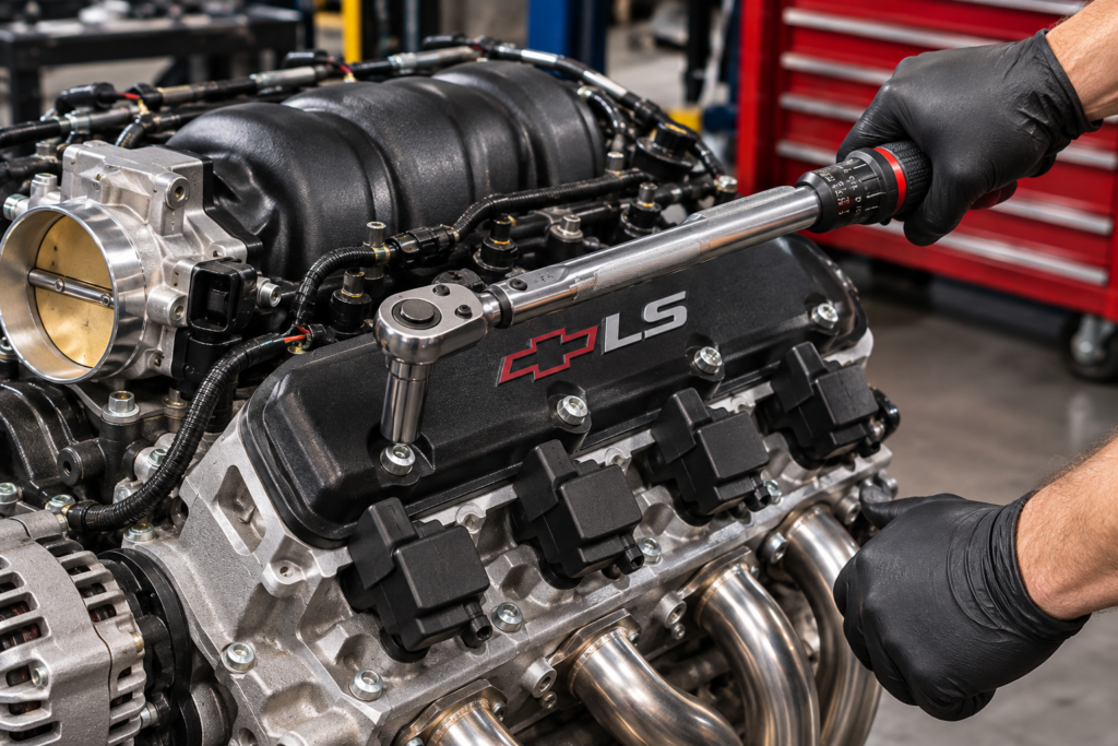
LS engine torque specs vary by engine generation, fastener design, and component, but many Gen III and Gen IV LS engines share common tightening procedures. For example, standard LS rocker arm bolts are commonly tightened to 22 lb-ft (30 Nm), intake manifold bolts use a two-stage sequence of 44 in-lb followed by 89 in-lb, and cylinder head bolts typically begin at 22 lb-ft before additional angle-tightening passes.
However, there is no single torque specification that applies to every LS engine bolt. Critical fasteners such as cylinder head bolts, connecting rod bolts, main bearing cap bolts, and crankshaft balancer bolts often require torque-to-yield procedures involving several stages of tightening.
The Chevrolet LS engine family includes the LS1, LS2, LS3, LS6, LS7, LS9, LSA, and numerous truck-based V8 engines such as the 4.8L LR4, 5.3L LM7, and 6.0L LQ4 and LQ9. Although these engines share fundamental architectural features, their fastener designs and tightening requirements are not identical.
One especially important difference involves cylinder head bolts. Earlier LS engines used different lengths of M11 head bolts, while a design change during the 2004 production period introduced a different bolt arrangement and tightening procedure. General Motors also issued a service bulletin revising connecting rod bolt tightening angles for many Gen III and Gen IV V8 applications.
Correct torque is essential for achieving the required clamping force, maintaining gasket sealing, protecting bearing clearances, and preventing mechanical failure. This guide explains the most common factory-style LS torque specifications, how tightening sequences work, and why the exact engine code and fastener manufacturer must be verified before assembly.
What Are the Most Common LS Engine Torque Specs?
Common factory-style Gen III and Gen IV LS torque specifications include 22 lb-ft for rocker arm bolts, 44 and 89 in-lb for the two intake manifold tightening passes, 18 lb-ft for many timing cover bolts, and 106 in-lb for valve cover bolts. Critical internal fasteners generally require additional tightening procedures.
The standard LS cylinder head bolt procedure typically begins with 22 lb-ft on the large M11 bolts.
A second pass adds 90 degrees of rotation.
The final tightening angle depends on the cylinder head bolt design and engine configuration.
For certain earlier LS engines, the long M11 bolts receive another 90 degrees while the shorter M11 bolts receive an additional 50 degrees.
Later conventional LS arrangements commonly use an additional 70 degrees for the M11 bolts.
The smaller M8 head bolts are generally tightened to 22 lb-ft after the larger bolts have received their required passes.
Main bearing cap fasteners also use torque-angle procedures.
For several conventional LS configurations, the inner main cap bolts begin at 15 lb-ft followed by 80 degrees.
The outer main cap studs begin at 15 lb-ft and receive a further angle specified for the particular engine.
Main cap side bolts commonly require 18 lb-ft.
Standard connecting rod bolts in many later Gen III and Gen IV applications use an initial 15 lb-ft followed by 85 degrees under GM’s revised service specification.
However, some early rod bolt designs use a different final angle.
These figures are useful references, but they do not replace the service instructions for the exact engine.
Aftermarket bolts and studs can require completely different tightening procedures.
Why Do LS Engine Torque Specifications Vary?
LS torque specifications differ because General Motors changed fastener designs, engine components, materials, and assembly procedures throughout the development of the Gen III and Gen IV small-block V8 families.
The LS engine architecture entered production with the 1997 Chevrolet Corvette.
The original LS1 introduced a modern aluminum V8 design featuring deep-skirt block construction, cross-bolted main bearing caps, and improved cylinder head technology.
General Motors subsequently expanded the engine family.
The LS6 incorporated performance-focused changes, while the LS2 increased displacement to 6.0 liters.
The LS3 introduced a 6.2-liter configuration with rectangular-port cylinder heads.
The LS7 used a substantially different 7.0-liter performance configuration, and the LS9 and LSA introduced supercharging.
Truck-based LS engines also evolved across generations.
The 4.8L, 5.3L, and 6.0L variants were produced with different blocks, rotating assemblies, cylinder heads, and electronic systems.
Although many fasteners are shared across these engines, several critical applications use engine-specific hardware.
Cylinder head bolts are a major example.
The original head bolt arrangement was revised during the 2004 production period, changing both the installed bolt lengths and final tightening angles.
Connecting rod bolts also received updated service information.
The crankshaft balancer installation procedure differs between certain LS1, LS3, and LS7 applications.
Camshaft sprocket fasteners can also vary depending on whether the engine uses a conventional three-bolt camshaft gear or a single-bolt arrangement.
For this reason, the correct torque specification should be identified using the engine code, production configuration, and actual fastener design.
LS1 and LS6 Cylinder Head Bolt Torque Specs
For first-design LS1 and LS6 cylinder head bolts, the M11 bolts are tightened to 22 lb-ft, followed by an additional 90 degrees. The final pass adds 90 degrees to the eight long M11 bolts and 50 degrees to the two medium-length M11 bolts on each cylinder head.
This procedure applies to the early unequal-length head bolt arrangement.
The original LS cylinder head fastening system uses M11 bolts of different lengths.
Each cylinder head has eight longer M11 bolts and two medium-length M11 bolts, along with five smaller M8 bolts.
The larger fasteners provide the principal clamping force between the cylinder head and block.
The shorter M8 bolts support the surrounding joint.
The first tightening pass seats the cylinder head and begins establishing the required clamping load.
The second pass rotates the M11 fasteners an additional 90 degrees in the specified sequence.
The third pass is different for the two M11 bolt lengths.
The eight longer bolts receive another 90 degrees, while the two medium-length bolts receive 50 degrees.
After the M11 tightening procedure is completed, the five M8 bolts are tightened to 22 lb-ft.
The M8 bolts are installed in their specified sequence, beginning near the center and working outward.
These figures are based on the first-design fastener configuration documented by the AERA Engine Builders Association.
The tightening sequence and correct bolt locations are as important as the numerical values.
A bolt installed in the wrong hole may not engage correctly or may damage the block.
The original torque-to-yield cylinder head bolts must be replaced rather than reused after removal.
LS2 and LS3 Cylinder Head Bolt Torque Specs
For the common second-design LS2 and LS3 cylinder head bolt arrangement, the M11 bolts are tightened to 22 lb-ft, followed by 90 degrees and then another 70 degrees. The smaller M8 bolts are tightened to 22 lb-ft after the M11 procedure is completed.
The second-design arrangement differs from the earliest LS cylinder head fastening system.
During the 2004 production period, GM changed the M11 bolt arrangement.
The later design generally uses ten M11 bolts of the same approximately 100 mm length per cylinder head instead of the earlier combination of long and medium-length bolts.
This change also affects the threaded hole depths in the engine block.
The initial tightening pass remains 22 lb-ft.
The second pass adds 90 degrees of rotation.
The final pass adds 70 degrees to the M11 bolts.
The five smaller M8 bolts are then tightened to 22 lb-ft.
This procedure is commonly associated with conventional second-design Gen IV LS applications, including the LS2 and LS3.
However, performance variants with different head bolt diameters or specialized fasteners must be treated separately.
The LS9 and LSA, for example, should not automatically receive the standard LS3 cylinder head torque procedure.
The correct bolt design must also be confirmed on any engine assembled from mixed components.
An LS swap may combine a block and cylinder heads from different vehicles or production years.
The installed fasteners and block design ultimately determine the appropriate procedure.
What Changed in LS Head Bolts During 2004?
GM introduced a cylinder head bolt design change during the 2004 production period, replacing an arrangement with unequal-length M11 bolts with a second design using M11 bolts of a common length.
This distinction is especially important for builders working with early LS blocks.
The AERA Engine Builders Association published a technical bulletin identifying the differences.
The first-design engine uses M11 bolts approximately 155 mm and 100 mm long.
The second-design block uses M11 bolts approximately 100 mm long.
The threaded hole depths were also changed.
For the first design, the long bolts use a different final tightening angle from the shorter M11 bolts.
For the second design, the conventional procedure uses the same 70-degree final angle for all ten M11 bolts on each cylinder head.
Because the design transition occurred during a production period, model year alone is not always sufficient for identifying the correct hardware.
An engine assembled in early 2004 may use different head bolts from one produced later.
Replacement engine blocks and previously rebuilt engines can create additional uncertainty.
The correct approach is to inspect the block’s fastening arrangement and obtain bolts intended for that configuration.
Bolts should not be substituted simply because their thread diameter appears compatible.
A bolt that is too long can bottom out in a blind hole before achieving the required cylinder head clamping force.
The resulting condition can damage threads, distort components, or create head gasket sealing problems.
Identifying the correct head bolt design is essential before applying any published LS torque sequence.
What Is the Correct LS Cylinder Head Tightening Sequence?
LS cylinder head bolts must be tightened in the manufacturer’s prescribed sequence, generally beginning with the central fasteners and progressing outward to distribute clamping force evenly across the head gasket.
The cylinder head must seal combustion pressure while separating coolant and engine oil passages.
Uneven tightening can distort the cylinder head or create inconsistent gasket compression.
The conventional LS head bolt arrangement uses ten large M11 fasteners and five smaller M8 fasteners on each cylinder head.
The manufacturer assigns positions to these bolts for tightening.
The large bolts are completed through the applicable staged torque-angle procedure.
The smaller bolts are tightened afterward.
This is different from simply tightening each bolt completely before moving to the next one.
During the first pass, all applicable M11 bolts are brought to the specified initial torque.
The subsequent angle passes are completed in the required order.
Each tightening stage progressively increases the clamping force.
A torque-angle gauge is required because the later stages specify rotational movement rather than a final torque wrench reading.
The head gasket and fastener manufacturer may also provide specific surface preparation requirements.
Threaded holes should be clean and free of trapped liquids or debris.
The cylinder head and engine block sealing surfaces must meet the required flatness and finish specifications.
The correct sequence should be obtained from the service manual or the fastener manufacturer’s instructions.
Although the general center-out approach is useful for understanding the process, it is not a substitute for the exact numbered tightening diagram.
LS Main Bearing Cap Torque Specs
For many conventional Gen III and Gen IV LS engines, the inner main bearing cap bolts use an initial 15 lb-ft followed by 80 degrees, while the outer main cap studs use 15 lb-ft followed by an engine-specific final angle. Main cap side bolts commonly require 18 lb-ft.
The LS engine uses a deep-skirt block design with cross-bolted main bearing caps.
This arrangement helps support the crankshaft under combustion and rotational loads.
The main bearing caps must be installed with the correct orientation and in their original or properly machined locations.
Bearing clearances are established through the relationship between the crankshaft journals, bearing shells, block, and main caps.
Incorrect clamping force can affect that relationship.
The inner main cap bolts on many LS engines are tightened first to 15 lb-ft, then rotated an additional 80 degrees.
The outer main cap studs or bolts may use a similar initial torque, followed by an additional angle.
Early LS1 and LS6 references commonly specify approximately 53 degrees for the outer studs.
Certain later LS2, LS3, and LS7 references specify approximately 51 degrees.
The cross-bolted side fasteners commonly require 18 lb-ft.
However, the exact procedure should correspond to the engine’s main bearing cap design and fastener arrangement.
Some engine variants use different bolt dimensions, and aftermarket engine blocks may have unique requirements.
The main bearing caps should also be tightened in the proper sequence.
After assembly, the crankshaft should rotate freely with the appropriate bearing clearance.
Correct fastener torque is essential, but it does not replace mechanical measurements during engine assembly.
LS Connecting Rod Bolt Torque Specs
For many factory Gen III and Gen IV LS connecting rod bolts, GM’s revised service procedure specifies an initial 15 lb-ft followed by an additional 85 degrees. However, certain early connecting rod bolt designs use different procedures.
Connecting rod bolts are among the most highly stressed fasteners inside an engine.
They retain the connecting rod cap around the crankshaft journal.
During operation, the rod assembly experiences repeated loading as the piston accelerates and decelerates.
Insufficient bolt clamping force can allow movement at the connecting rod cap joint.
Excessive tightening can stretch or damage the bolt.
A GM service bulletin issued on March 5, 2007, revised the connecting rod tightening procedure for numerous Gen III and Gen IV Vortec V8 engines.
Bulletin 07-06-01-002 increased the final tightening angle from 75 degrees to 85 degrees for the covered applications.
The specified initial torque remains 15 lb-ft, equivalent to approximately 20 Nm.
However, this bulletin does not establish that all LS connecting rod designs use exactly the same procedure.
Certain early first-design rod bolts have separate specifications, commonly identified as 15 lb-ft followed by 60 degrees.
The LS7 and some specialized engines also require attention to their own service procedures.
Aftermarket connecting rods may use entirely different bolt types.
Performance rod manufacturers often specify bolt stretch or a particular torque using a recommended lubricant.
The factory GM connecting rod torque procedure should never be applied blindly to aftermarket fasteners.
For an engine rebuild, the actual rod and bolt manufacturer should be identified before assembly.
LS Rocker Arm Bolt Torque Specs
The standard rocker arm bolt torque specification for many Gen III and Gen IV LS engines is 22 lb-ft (30 Nm).
This is one of the most commonly used LS engine torque values.
The LS engine family uses an overhead-valve arrangement.
A camshaft positioned in the engine block operates hydraulic lifters and pushrods, which transfer motion to the rocker arms.
The rocker arms then open the intake and exhaust valves.
Correct rocker arm fastening is important because these components repeatedly experience valvetrain loading.
A loose rocker arm can create noise, inaccurate valve motion, or mechanical damage.
Excessive tightening can damage the mounting threads or associated components.
The standard 22 lb-ft specification applies to many factory-style rocker arm mounting bolts.
However, the installation procedure must be performed with attention to camshaft position.
Depending on the engine’s service instructions, certain rocker arms should be installed or tightened when the related lifter and camshaft are positioned appropriately.
This reduces the risk of creating excessive valve spring loading during assembly.
The pushrods must also be correctly positioned in the lifters and rocker arm seats.
Incorrect pushrod positioning can damage valvetrain components when the engine rotates.
Aftermarket shaft-mounted rocker systems, upgraded trunnion assemblies, or nonstandard rocker fasteners may require different torque values.
The manufacturer’s specification takes precedence over the factory 22 lb-ft reference.
LS Intake Manifold Torque Specs
The common factory LS intake manifold bolt procedure uses two stages: 44 in-lb (5 Nm) during the first pass and 89 in-lb (10 Nm) during the final pass.
This procedure is used across many LS1, LS2, LS3, LS6, and LS7 intake manifold applications.
The intake manifold directs air into the engine’s cylinders.
Its sealing surfaces must maintain an airtight connection with the cylinder heads.
Vacuum leaks can occur if the manifold gaskets are damaged, incorrectly installed, or subjected to uneven clamping force.
The relatively low tightening torque reflects the design of the manifold and mounting fasteners.
Many factory LS intake manifolds are made from composite materials.
These components can be damaged if excessively tightened.
The first pass of 44 in-lb establishes initial gasket compression.
The second pass increases the torque to 89 in-lb.
The bolts are tightened in the prescribed sequence, generally progressing outward from the central area.
A small torque wrench calibrated in inch-pounds is preferable for this operation.
Using a large foot-pound torque wrench may reduce accuracy at these relatively low values.
The units are especially important.
Eighty-nine inch-pounds is approximately 7.4 foot-pounds.
Applying 89 foot-pounds instead would create a vastly different clamping load and could damage the manifold or cylinder head threads.
Aftermarket intake manifolds may use different fasteners and installation procedures.
If the intake manufacturer supplies its own torque specification, that information should be followed.
LS Exhaust Manifold Torque Specs
Common LS exhaust manifold tightening procedures begin at 11 lb-ft, with a final pass of approximately 18 lb-ft on certain earlier LS engines and 15 lb-ft on several later applications.
The exhaust manifold carries hot combustion gases from the cylinder head toward the exhaust system.
In factory configurations, the manifold is designed to maintain sealing under repeated heating and cooling cycles.
The bolts must withstand thermal expansion while keeping the manifold correctly positioned against the cylinder head.
On various LS1 and LS6 applications, published service information identifies an initial 11 lb-ft followed by a final 18 lb-ft.
For certain LS2, LS3, and LS7 configurations, the final pass is listed at 15 lb-ft.
These differences are important because the engines do not all use identical exhaust arrangements.
The specified tightening sequence should also be followed.
Starting near the central fasteners and progressing outward can help distribute clamping force, but the exact sequence should match the service instructions.
Exhaust manifold bolts may become difficult to remove after years of exposure to heat and corrosion.
Improper removal can break a bolt inside the cylinder head.
During installation, the threads and sealing surfaces should be inspected.
A damaged manifold or distorted sealing surface may continue leaking even when the bolts are tightened correctly.
Aftermarket headers may use different flange thicknesses, fasteners, or gasket arrangements.
Their manufacturers may specify different torque values or additional heat-cycle inspection procedures.
A factory LS exhaust manifold specification should not automatically be used for every aftermarket header installation.
LS Crankshaft Balancer Bolt Torque Specs
The crankshaft balancer bolt is one of the most important LS fasteners, and its installation procedure varies substantially between engine configurations.
For certain LS1, LS2, and LS6 applications, the published procedure includes an initial balancer seating operation using an installation bolt or suitable installation method.
A commonly documented seating torque is 240 lb-ft.
However, this should not be confused with the final tightening specification for the new production balancer bolt.
After the balancer has been correctly seated, the installation bolt is removed and the required new fastener is installed.
For these applications, the new bolt receives an initial 37 lb-ft followed by an additional 140 degrees.
The LS3 uses a different procedure for certain factory balancer bolt designs.
Published service information identifies an initial seating operation at 110 lb-ft, followed by loosening the bolt one full turn.
The bolt is then tightened to 59 lb-ft and rotated an additional 125 degrees when using the specified flanged-head bolt.
The LS7 has another procedure.
Its published figures include an initial 111 lb-ft, loosening 360 degrees, tightening to 59 lb-ft, and a final 200-degree rotation.
These figures demonstrate why the balancer bolt cannot be assigned one universal LS torque specification.
The fastener design, washer configuration, and exact engine instructions must be verified.
A properly installed harmonic balancer is essential for reliable crankshaft operation.
An incorrectly seated balancer or improperly tightened bolt can cause movement, vibration, or damage.
The correct installation tool and specified new torque-to-yield bolt should be used where required.
Read more: Short Block vs Long Block
LS Flywheel and Flexplate Torque Specs
For common factory LS1 and LS6 flywheel applications, a published tightening procedure uses 15 lb-ft for the first pass, 37 lb-ft for the second pass, and 74 lb-ft for the final pass.
The flywheel or flexplate connects the crankshaft to the transmission system.
Manual-transmission engines use a flywheel to support clutch operation.
Automatic-transmission engines generally use a flexplate connected to the torque converter.
These components experience repeated torque loading during acceleration, deceleration, and gear changes.
Their mounting fasteners must maintain the correct clamping force against the crankshaft flange.
A loose flywheel or flexplate can produce noise, vibration, or severe drivetrain damage.
The staged tightening procedure helps distribute the clamping load across the crankshaft flange.
The bolts should be tightened in the prescribed alternating pattern rather than completely tightening adjacent bolts one after another.
However, not every LS flywheel or flexplate combination uses the same fastening procedure.
Engine model, crankshaft design, transmission type, and replacement hardware can influence the requirements.
Some aftermarket flywheels and flexplates also use specialized bolts.
These may require different lubricants, threadlocking compounds, or tightening specifications.
A performance flywheel supplied with aftermarket hardware should be installed according to the component manufacturer’s instructions.
The bolt length is also important.
An incorrect bolt can interfere with surrounding components or fail to provide adequate thread engagement.
For an LS swap, both the flywheel or flexplate compatibility and fastener specification should be confirmed before installation.
LS Camshaft and Timing Component Torque Specs
Common LS timing component specifications include 18 lb-ft for a standard camshaft retainer plate, 26 lb-ft for certain three-bolt camshaft sprockets, and a torque-angle procedure for certain single-bolt camshaft arrangements.
Camshaft fasteners are critical because they maintain the relationship between crankshaft rotation and valve timing.
The camshaft retainer plate prevents unwanted longitudinal movement of the camshaft.
Many standard hex-head retainer plate bolts are tightened to 18 lb-ft.
However, certain countersunk Torx or hex fastener designs require approximately 11 lb-ft.
This distinction should be verified before assembly.
The camshaft sprocket also has multiple designs.
Conventional three-bolt camshaft sprocket arrangements commonly use 26 lb-ft for the bolts.
Certain single-bolt camshaft configurations use an initial 55 lb-ft followed by an additional 50 degrees.
These arrangements are not interchangeable from a fastening standpoint.
Single-bolt camshaft systems may also use variable valve timing equipment.
A VVT phaser and its mounting fastener require the procedure specified for that application.
A camshaft conversion kit may provide new hardware and its own tightening instructions.
Using the torque specification from a three-bolt sprocket on a single-bolt configuration can create serious problems.
The timing chain, camshaft sprocket, crankshaft sprocket, and related components must also be installed correctly.
Incorrect timing may cause poor performance or, in certain combinations, piston-to-valve contact.
For a camshaft replacement, the appropriate engine-specific service procedure should be followed rather than relying on an abbreviated generic LS torque chart.
LS Oil Pan, Oil Pump, and Timing Cover Torque Specs
For many conventional LS engines, oil pan M8 bolts are tightened to 18 lb-ft, smaller M6 oil pan-to-rear-cover fasteners use approximately 106 in-lb, and oil pump-to-block bolts commonly require 18 lb-ft.
The LS lubrication system depends on properly assembled sealing surfaces and secure oil pump installation.
The engine oil pump supplies pressurized lubricant to the crankshaft bearings, camshaft components, lifters, and other internal surfaces.
Its mounting bolts must maintain the correct position against the engine block.
Many common LS applications specify approximately 18 lb-ft for the oil pump mounting bolts.
The oil pickup tube must also be secured correctly.
A commonly published torque figure for the oil pickup tube retaining fastener is approximately 106 in-lb.
However, certain engine configurations use different pickup components or fastening arrangements.
The oil pan also uses several bolt sizes.
The larger M8 fasteners are commonly tightened to 18 lb-ft.
Smaller M6 bolts connecting the oil pan to the rear engine cover may require approximately 106 in-lb.
These values should not be interchanged.
The front engine cover often uses a nominal 18 lb-ft specification for its principal bolts.
Other cover fasteners or specialized configurations may differ.
Correct sealing depends on more than fastener torque.
The mating surfaces must be clean, the gasket must be positioned properly, and any specified sealant must be applied in the correct locations.
Excessive tightening can damage aluminum threads or distort sealing surfaces.
A leak that persists after correct installation may indicate a damaged gasket, distorted component, or improper sealant application rather than insufficient bolt torque.
LS Valve Cover and Valley Cover Torque Specs
Factory-style LS valve cover bolts commonly require 106 in-lb, equivalent to approximately 12 Nm, while many conventional valley cover fasteners use 18 lb-ft.
Valve covers seal the upper portion of the cylinder heads.
They help retain engine oil and prevent contamination from entering the valvetrain.
The valve cover gasket is designed to seal with a relatively modest clamping load.
Excessive tightening can distort the cover or damage the sealing arrangement.
This is especially important because many LS valve cover bolts use sealing grommets or related components.
The published 106 in-lb figure is relatively low.
Using a foot-pound torque wrench without checking the units can lead to substantial over-tightening.
The engine valley cover is installed between the cylinder banks.
Its design varies according to engine generation and application.
Some Gen IV engines use valley covers associated with Active Fuel Management oil control components.
These arrangements have additional parts and potentially different installation details.
Although 18 lb-ft is a common general reference for conventional valley cover bolts, the exact application must be verified.
Engine builders should also confirm gasket placement and sealing surface condition.
A cover that is distorted or installed with a damaged gasket can leak even when the bolts are tightened to the published specification.
For aftermarket valve covers, billet valley covers, or modified AFM components, the supplier’s instructions take precedence.
LS Water Pump and Thermostat Housing Torque Specs
Many factory Gen III and Gen IV LS water pump installations use an initial 11 lb-ft pass followed by a final 22 lb-ft pass. Thermostat housing bolts commonly require approximately 11 lb-ft.
The water pump circulates coolant through the engine and radiator.
Its correct installation is important because coolant loss or reduced circulation can cause overheating.
The water pump fasteners must compress the gasket or sealing system evenly against the engine block.
A staged tightening procedure helps distribute the load.
An initial 11 lb-ft pass is commonly followed by a final tightening pass to 22 lb-ft.
However, the exact procedure depends on the water pump and engine configuration.
Aftermarket water pumps may use different fasteners or mounting arrangements.
The thermostat housing uses smaller fasteners in many applications.
A common specification is 11 lb-ft.
However, the housing design and fastener material should be confirmed before tightening.
Excessive torque can damage aluminum threads or crack certain housings.
The cooling system should also be inspected before reassembly.
A worn water pump bearing, damaged gasket surface, or faulty thermostat cannot be corrected merely by applying additional torque.
For an engine rebuild or LS swap, the water pump must also match the vehicle’s accessory drive spacing and cooling system connections.
Correct component compatibility and sealing are as important as the tightening specification.
LS Spark Plug Torque Specs
A common LS spark plug tightening specification for replacement plugs installed in previously used cylinder heads is 11 lb-ft (15 Nm), although initial installation values and aftermarket plug requirements can differ.
Spark plugs create the electrical spark needed to ignite the air-fuel mixture.
They thread into the cylinder heads and must maintain appropriate sealing and heat transfer.
Correct installation torque prevents the plug from becoming loose while avoiding damage to the cylinder head threads.
Aluminum cylinder heads require particular care.
Over-tightening can strip threads or damage the spark plug seat.
Under-tightening may cause combustion gas leakage or improper heat transfer.
Many published LS service references identify 11 lb-ft for subsequent spark plug installation.
However, some procedures distinguish between the initial installation of plugs into new cylinder heads and later replacement.
The required torque can also depend on the spark plug’s seating arrangement, thread size, and manufacturer.
NGK, ACDelco, and other suppliers may publish product-specific instructions.
The installation should be performed according to the actual plug and engine requirements.
Spark plugs should be started by hand to avoid cross-threading.
The use of anti-seize compounds should not be assumed.
Some spark plug manufacturers advise against additional anti-seize on plugs with suitable factory-applied thread coatings because lubrication can change the relationship between torque and clamping force.
The manufacturer’s instructions are the correct reference when this issue arises.
Are LS Engine Torque Specs the Same for 4.8, 5.3, and 6.0 Engines?
Many 4.8L, 5.3L, and 6.0L LS-based truck engines share common tightening values, but their exact procedures depend on engine generation, production period, and fastener configuration.
GM produced numerous truck-based Gen III and Gen IV V8 engines.
Popular examples include the 4.8L LR4, 5.3L LM7, and 6.0L LQ4 and LQ9.
Later engine families introduced additional variations, including engines such as the LC9, LY6, and L96.
These powerplants share important LS architecture characteristics.
Many use the same general deep-skirt block arrangement and cross-bolted main caps.
Consequently, a number of commonly referenced torque specifications are similar.
Rocker arm bolts are often tightened to 22 lb-ft.
Intake manifold fasteners commonly use the 44 and 89 in-lb two-stage procedure.
Main cap inner bolts frequently use a 15 lb-ft initial pass followed by 80 degrees.
However, the cylinder head bolt procedure may differ across production periods.
Earlier blocks with unequal-length M11 head bolts require a different final tightening sequence from later second-design blocks.
Connecting rod bolt specifications also require attention to GM’s updated service information.
The company revised the final angle for many Gen III and Gen IV rod bolts through a service bulletin.
Certain truck engines also use specialized valvetrain or variable valve timing components.
These introduce additional installation requirements.
The most accurate way to identify the correct torque specifications is through the engine’s RPO code, production information, and relevant GM service documentation.
A generic 5.3L torque chart should not automatically be applied to every engine with that displacement.
Are LS1, LS2, LS3, and LS7 Torque Specs Interchangeable?
No. Although LS1, LS2, LS3, and LS7 engines share fundamental small-block architecture, some critical fasteners and installation procedures differ.
The LS1 and LS6 are Gen III engine families.
The LS2, LS3, and LS7 belong to the subsequent Gen IV development period.
Many common service components retain similar tightening values.
Examples include rocker arm bolts, certain intake manifold fasteners, and several external covers.
However, critical differences remain.
Cylinder head bolt length and final tightening angle changed during the development of the engine family.
The LS7 also uses specialized components designed for its 7.0-liter high-performance configuration.
Its crankshaft balancer procedure differs from the common LS1 arrangement.
Main cap fasteners and other components also require attention to the specific engine design.
The LS9 and LSA introduce additional complexity because of their supercharged configurations.
Their cylinder head fasteners and other engine-specific components should not automatically receive conventional naturally aspirated LS procedures.
The same applies to aftermarket LSX blocks and performance crate engines.
An engine assembled from a combination of OEM and aftermarket parts may have no single factory torque chart that covers every fastener.
For example, a builder may use a factory LS3 block with aftermarket connecting rods, ARP main studs, upgraded cylinder heads, and a different camshaft sprocket.
Each fastener group may require its own manufacturer’s specification.
Correct assembly depends on identifying the actual components rather than assuming every engine called an LS uses identical hardware.
What Is Torque-to-Yield on an LS Engine?
Torque-to-yield is a fastening method in which a bolt is tightened using an initial torque followed by controlled angular rotation that stretches the fastener to achieve the intended clamping force.
Many factory LS cylinder head bolts are torque-to-yield fasteners.
Certain connecting rod and crankshaft balancer bolts also use torque-angle procedures involving single-use hardware.
The method differs from tightening a conventional reusable bolt to one fixed torque value.
A standard torque wrench measures the rotational force applied during tightening.
However, friction between threads and under the bolt head influences how much of that torque becomes useful clamping force.
Torque-angle procedures can reduce some of the variation associated with thread friction by controlling bolt rotation after the joint has been seated.
The initial torque establishes contact between the components.
The subsequent angular movement stretches the bolt according to the manufacturer’s procedure.
For example, a head bolt may first be tightened to 22 lb-ft.
The next pass rotates it an additional 90 degrees.
A final pass may add another 70 degrees or a different specified amount.
These angle values are additional rotations, not final torque readings.
A 90-degree turn represents one-quarter of a complete revolution.
A 70-degree turn represents a smaller angular movement.
It is important to recognize that not every fastener using a torque-angle procedure is necessarily interchangeable with another fastener using the same method.
Different bolts have different lengths, diameters, materials, and tightening requirements.
Factory torque-to-yield bolts should be replaced when the service instructions identify them as single-use fasteners.
Reusing a bolt that has already been stretched beyond its intended reusable range may prevent it from achieving the necessary clamping force.
Can You Reuse LS Head Bolts, Rod Bolts, and Balancer Bolts?
Factory LS cylinder head bolts are generally single-use torque-to-yield fasteners and should be replaced after removal. Connecting rod and crankshaft balancer bolt reuse depends on the specific fastener and applicable service instructions.
The most important principle is that bolt reuse must be determined by fastener design.
Some engine bolts remain within their elastic range when tightened correctly.
These fasteners can sometimes be reused if they remain undamaged and the manufacturer permits it.
Torque-to-yield bolts are different.
Their tightening procedure intentionally stretches the fastener to develop the required clamping load.
After removal, the bolt may no longer behave as intended during another installation.
This is why conventional factory LS head bolts are replaced rather than reused.
The same caution applies to several factory connecting rod and balancer fasteners.
An incorrect reuse decision can have serious consequences.
Loss of cylinder head clamping force can cause gasket leakage.
A connecting rod bolt failure can destroy the rotating assembly.
A loose crankshaft balancer can damage the crankshaft interface or related components.
Aftermarket hardware introduces another consideration.
Certain performance bolts and studs are designed for reuse when they remain within the manufacturer’s inspection limits.
However, reusable does not mean unlimited reuse.
The fastener manufacturer may specify inspection for permanent stretch, thread damage, or other defects.
The correct procedure should be based on the exact fastener part number rather than a general statement about all LS engine bolts.
Do ARP Head Studs and Main Studs Use Factory LS Torque Specs?
No. ARP head studs, main studs, and connecting rod fasteners should be installed using the torque or bolt-stretch specifications supplied by ARP for the exact kit. Factory GM torque-to-yield procedures do not automatically apply.
Performance LS engines often use aftermarket fasteners.
These components may be manufactured from different materials and designed around different clamping requirements.
ARP produces head bolts, head studs, main studs, and connecting rod bolts for various LS applications.
The required installation procedure can depend on the material grade, fastener dimensions, nut configuration, washer design, and lubricant.
ARP also supplies its own Ultra-Torque fastener lubricant for specified installations.
Lubrication matters because friction influences the relationship between tightening torque and the clamping force developed in the bolt or stud.
Applying the same torque to a dry fastener and a lubricated fastener may produce significantly different clamping forces.
For this reason, a torque value cannot always be transferred from one fastener design to another.
Head stud installation also differs mechanically from conventional head bolt installation.
A stud is threaded into the block, while a nut is tightened against the cylinder head through a washer.
The specified procedure controls the load applied through the nut.
The manufacturer’s instructions may define whether the stud should be installed hand-tight and which lubricant should be applied to the threads and washers.
Some ARP connecting rod bolts are installed using measured stretch rather than a conventional torque-only method.
A bolt stretch gauge can provide information about the actual elongation of the fastener.
The correct specification should come directly from the fastener kit instructions.
Using a generic LS torque chart for aftermarket studs can produce incorrect clamping force and potentially damage the engine.
Does Thread Lubricant Affect LS Torque Specifications?
Thread lubrication affects tightening torque because friction determines how much applied rotational force becomes useful fastener clamping force.
The specified tightening procedure assumes particular thread and contact conditions.
Some fasteners are installed dry.
Others require engine oil, threadlocker, sealant, or a dedicated assembly lubricant.
Changing these conditions can affect the final clamping load.
For example, adding lubricant to a fastener intended to be tightened dry can reduce friction.
At the same torque reading, the bolt may stretch more than expected.
Conversely, excessive friction can prevent the required clamp load from being achieved.
This is especially important for high-load fasteners such as head studs, connecting rod bolts, and main studs.
Thread preparation also matters.
Dirty or damaged threads can produce inconsistent tightening behavior.
Blind threaded holes must be checked for trapped fluid.
If a hole contains oil or coolant, installing a bolt may create hydraulic pressure near the bottom of the hole.
In severe cases, this can damage the surrounding material.
Thread chasers may be used where appropriate to clean threads without unnecessarily removing material.
However, thread repair and cleaning procedures should follow the engine manufacturer’s guidance.
Sealant requirements also vary.
Certain threaded holes communicate with fluid passages, while others do not.
The correct product and amount should be used where sealant is specified.
A torque specification should therefore always be interpreted together with thread condition, fastener material, and the manufacturer’s installation instructions.
How Do You Convert LS Torque Specs Between Foot-Pounds and Inch-Pounds?
LS torque specifications commonly use foot-pounds for major engine fasteners and inch-pounds for smaller bolts associated with intake manifolds, valve covers, sensors, and related components.
The distinction is important because the two units represent different amounts of torque.
One foot-pound is equal to twelve inch-pounds.
For example, the commonly specified 89 in-lb intake manifold final torque is equivalent to approximately 7.4 ft-lb.
The 106 in-lb valve cover specification is equivalent to approximately 8.8 ft-lb.
A torque wrench calibrated in foot-pounds may not provide its best accuracy at these relatively low settings.
A smaller inch-pound wrench is therefore often preferable.
Metric specifications use newton-meters.
The standard 22 lb-ft rocker arm specification is approximately 30 Nm.
The 15 lb-ft initial main cap torque is approximately 20 Nm.
The 18 lb-ft oil pump mounting specification is approximately 24 Nm, commonly rounded to 25 Nm in technical references.
However, the actual service manual conversion should be preferred when the manufacturer provides both values.
Rounded conversions can introduce small differences.
The most serious mistake is confusing inch-pounds with foot-pounds.
An intake bolt requiring 89 in-lb should not be tightened to 89 ft-lb.
That error would apply twelve times the intended torque.
Always check both the number and unit before tightening a fastener.
What Tools Do You Need to Torque an LS Engine Correctly?
Correct LS engine assembly requires calibrated torque tools capable of measuring both conventional tightening torque and specified angle rotations.
A conventional torque wrench is necessary for many engine fasteners.
However, the tool must operate accurately within the required torque range.
Small fasteners such as intake manifold and valve cover bolts require relatively low torque.
Large fasteners such as the crankshaft balancer bolt may require substantially greater torque.
Using one wrench for every operation may not provide sufficient accuracy across the complete range.
An inch-pound torque wrench is especially useful for low-torque components.
A larger torque wrench is appropriate for high-load fasteners.
A torque-angle gauge or electronic angle-measuring torque wrench is necessary for fasteners requiring additional angular rotation.
The angle should be measured accurately after the specified initial torque has been applied.
A breaker bar may be needed to complete certain high-angle tightening stages.
The engine must also be secured appropriately during assembly.
Crankshaft holding tools can prevent unwanted rotation when tightening a balancer or flywheel.
A harmonic balancer installation tool may be required to seat the balancer correctly before final bolt tightening.
Cylinder head bolt hole cleaning and preparation tools are also important.
For aftermarket connecting rod fasteners, a bolt stretch gauge may be required.
Torque tools should be maintained and calibrated according to their manufacturer’s recommendations.
The correct tools improve repeatability, but they do not replace the need to understand the proper sequence and fastener requirements.
What Happens If LS Engine Bolts Are Over-Torqued or Under-Torqued?
Incorrect bolt torque can cause gasket leaks, thread damage, distorted components, bearing problems, valvetrain faults, and severe internal engine damage.
Under-tightening occurs when the fastener does not provide sufficient clamping force.
For cylinder head bolts, inadequate clamping can allow combustion pressure or fluids to escape across the head gasket.
For main bearing caps, insufficient clamping may permit unwanted movement at the cap-to-block joint.
Connecting rod fasteners are especially critical because they experience repeated loading during engine operation.
A loose rod cap can cause bearing failure or catastrophic engine damage.
Over-tightening creates different risks.
Excessive bolt stretch can damage a fastener or reduce its remaining strength.
Threads inside an aluminum engine block or cylinder head may strip when subjected to excessive tightening force.
Small fasteners are particularly vulnerable.
Applying excessive torque to intake manifold bolts can damage the manifold or mounting threads.
Valve cover fasteners can distort sealing components.
Excessive tightening can also change the geometry of precision engine assemblies.
For example, main bearing cap fastener loading is related to the dimensions of the assembled bearing housing.
Incorrect clamping can affect bearing alignment and clearance.
The consequences are not always immediate.
An engine may initially start and operate before a poorly tightened component begins to leak or fail.
This is why correct torque procedures are essential during rebuilding.
Tightening bolts by feel alone is not appropriate for critical engine components.
How Can You Find the Correct Torque Specs for Your LS Engine?
The most reliable way to determine exact LS torque specifications is to identify the engine RPO code, production year, actual fastener configuration, and any aftermarket components before consulting the matching factory service instructions.
The LS family includes numerous configurations that can appear similar externally.
An LS1, LM7, LQ4, LS3, and LS7 all share elements of the same small-block development history.
However, they do not necessarily use identical fasteners.
The engine RPO code helps establish the original configuration.
The vehicle identification number can also help identify the engine installed by the manufacturer.
However, LS-swapped vehicles may contain engines from another model or year.
The actual block and components should therefore be inspected when necessary.
Cylinder head bolt design is a particularly important example.
An early engine may use unequal-length M11 bolts, while a later engine uses a different arrangement.
The correct procedure depends on that physical configuration.
Connecting rod bolt design is another important distinction.
General Motors issued revised specifications for many engines, making an old service manual potentially less accurate than updated technical information.
Aftermarket parts require separate verification.
ARP studs, aftermarket connecting rods, performance cylinder heads, and upgraded camshaft systems may use different tightening requirements.
A useful source is the GM service information corresponding to the vehicle or engine.
Chevrolet Performance also publishes installation guides for many crate engines.
Technical bulletins from GM and professional engine builder organizations can clarify known design changes.
The safest procedure is to verify the current instructions for the actual hardware rather than rely on a generalized LS torque chart.
Final Verdict: What Are the Correct LS Engine Torque Specs?
The most common LS engine torque specs include 22 lb-ft for factory rocker arm bolts, 44 in-lb followed by 89 in-lb for intake manifold bolts, 18 lb-ft for many front cover and oil pump mounting bolts, and 106 in-lb for conventional valve cover bolts.
Critical internal fasteners require more specific procedures.
Conventional LS cylinder head bolts generally begin at 22 lb-ft, followed by a 90-degree tightening pass.
The final angle depends on whether the engine has first-design or second-design head bolts.
Earlier engines with unequal-length M11 bolts commonly require another 90 degrees on the long bolts and 50 degrees on the shorter bolts.
Later second-design configurations commonly require another 70 degrees on the M11 bolts.
The smaller M8 head bolts are generally tightened to 22 lb-ft.
For many common LS main bearing cap configurations, the inner bolts use 15 lb-ft followed by 80 degrees.
Outer main studs also use staged tightening, while side bolts commonly require 18 lb-ft.
Many standard connecting rod bolts use 15 lb-ft followed by 85 degrees under GM’s revised service bulletin, but certain early and specialized designs use different procedures.
Crankshaft balancer bolts are especially important because the LS1, LS3, and LS7 can have different installation and final tightening requirements.
Aftermarket fasteners require additional attention.
ARP head studs, performance connecting rod bolts, and specialized main studs must be installed according to their own manufacturer’s specifications rather than automatically using factory torque-to-yield values.
The most important rule is to identify the exact LS engine and fastener before applying any torque specification. Correct bolt selection, thread preparation, tightening sequence, angle measurement, and component compatibility are essential for reliable engine assembly.
Using the appropriate factory service information and updated technical bulletins helps protect gasket sealing, bearing clearances, valvetrain operation, and long-term engine durability.