68RFE valve body replacement involves removing a faulty hydraulic control assembly and installing a compatible replacement to restore proper transmission operation. The 68RFE six-speed automatic transmission, commonly found in Ram 2500 and 3500 trucks equipped with the 6.7L Cummins diesel engine, relies on the valve body to regulate transmission fluid flow and control clutch engagement during gear changes.
Common signs of a failing 68RFE valve body include harsh shifting, delayed gear engagement, transmission slipping, and unexpected limp mode activation. These symptoms can result from worn hydraulic passages, sticking valves, or solenoid-related problems that disrupt transmission fluid pressure. However, similar symptoms can also indicate low fluid pressure, electrical faults, or internal clutch damage. Accurate diagnosis is essential before replacing the valve body.
Replacing a 68RFE valve body typically involves draining the transmission fluid, removing the transmission pan and filters, disconnecting the existing valve body, and installing the replacement assembly. The repair also requires proper fluid refilling, component compatibility checks, and post-installation testing. Total replacement costs depend on the valve body type, labor rates, and additional transmission service requirements.
This guide explains how to identify 68RFE valve body problems, confirm when replacement is necessary, complete the replacement process, compare repair costs, and verify transmission performance after installation.
What Is a 68RFE Valve Body and What Does It Do?
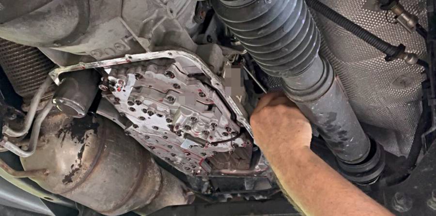
The 68RFE valve body is a hydraulic control assembly that regulates transmission fluid flow and directs hydraulic pressure to the clutch circuits inside the 68RFE six-speed automatic transmission. It works with the transmission control module (TCM) and electronically controlled solenoids to manage gear engagement, shift timing, and transmission operation. The assembly is located inside the transmission case, above the transmission fluid pan.
The 68RFE valve body contains hydraulic passages, control valves, and pressure-regulating components that distribute automatic transmission fluid (ATF) to specific clutch circuits. When the TCM commands a gear change, the solenoid pack controls hydraulic circuits within the valve body. Hydraulic pressure then applies or releases the appropriate clutch elements to establish the selected gear ratio. Accurate pressure regulation is essential because insufficient pressure can cause clutch slipping, while incorrect pressure timing can produce harsh or delayed shifts.
The valve body also works with the transmission’s pressure-control system to maintain appropriate clutch application under changing engine loads and driving conditions. For example, when a Ram 2500 accelerates while towing a trailer, the transmission must coordinate hydraulic pressure and clutch engagement to handle increased torque demand. Worn valve bores, sticking valves, or internal hydraulic leaks can interfere with this process, resulting in inconsistent shifting or reduced transmission performance.
The valve body and solenoid pack are related but distinct components. The valve body routes hydraulic fluid, while the solenoid pack electronically controls specific hydraulic functions. A malfunction in either component can produce similar transmission symptoms, making diagnostic testing necessary before replacing the complete valve body assembly.
What Are the Symptoms of a Bad 68RFE Valve Body?
The 5 main symptoms of a bad 68RFE valve body are harsh shifting, delayed gear engagement, transmission slipping, limp mode activation, and transmission-related diagnostic trouble codes (DTCs). These symptoms develop when worn hydraulic valves, internal pressure leaks, or restricted fluid passages interfere with clutch engagement and gear changes. However, similar problems can also result from faulty solenoids, electrical issues, or worn internal transmission components.
1. Harsh or Erratic Shifting
Harsh shifting occurs when the 68RFE transmission applies or releases clutch elements with incorrect hydraulic pressure or timing. Worn valve bores, sticking control valves, and internal fluid leaks can disrupt pressure regulation, causing abrupt gear changes or noticeable jolts during acceleration and deceleration. For example, a Ram 2500 may experience a pronounced shift shock during an upshift even under moderate throttle input. Repeated harsh shifts require diagnosis because excessive clutch engagement shock can increase stress on internal transmission components.
2. Delayed Gear Engagement
Delayed engagement occurs when the transmission takes longer than expected to engage Drive or Reverse after the driver moves the gear selector. The valve body must direct pressurized transmission fluid to the appropriate clutch circuits before the transmission can transfer engine torque. Internal hydraulic leakage or a sticking valve can delay pressure buildup and clutch application. For example, a Ram 3500 may pause after shifting from Park into Drive before the truck begins moving. Low transmission fluid, pump problems, and worn clutch seals can produce the same symptom.
3. Transmission Slipping
Transmission slipping occurs when engine speed increases without a corresponding increase in vehicle speed because the transmission cannot maintain sufficient clutch holding capacity. A malfunctioning 68RFE valve body can contribute to slipping by allowing hydraulic pressure to escape through worn valve bores or by failing to regulate clutch application correctly. Drivers may notice engine RPM rising during acceleration, particularly under heavy loads or while towing. Persistent slipping can overheat and damage clutch friction materials, making it essential to distinguish hydraulic control faults from existing internal clutch damage.
4. Limp Mode Activation
Limp mode is a protective operating strategy that restricts transmission functionality after the control system detects certain faults. A defective valve body can contribute to hydraulic pressure or gear-ratio errors that trigger this response. Depending on the detected fault and transmission control strategy, the truck may experience restricted gear selection, limited shifting, or reduced drivability. However, limp mode does not confirm valve body failure because solenoid faults, wiring problems, and internal mechanical damage can also trigger transmission protection strategies.
5. Transmission Warning Lights and Diagnostic Trouble Codes
Transmission-related diagnostic trouble codes indicate that the control system has detected an operating condition outside its expected parameters. Valve body problems can contribute to pressure-control and gear-ratio faults, including codes such as P0731 (Gear 1 Incorrect Ratio) or P0868 (Transmission Fluid Pressure Low). These codes identify symptoms or monitored conditions rather than proving that the valve body itself is defective. A technician must compare scan-tool data, transmission fluid condition, hydraulic pressure readings, and electrical test results before determining whether replacement is necessary.
The following table summarizes common 68RFE valve body failure symptoms and other transmission problems that require investigation.
| Symptom | Possible Valve Body Problem | Other Possible Causes |
|---|---|---|
| Harsh shifting | Sticking valves or incorrect hydraulic pressure regulation | Solenoid faults, adaptive shift issues |
| Delayed engagement | Internal hydraulic leakage or restricted valve movement | Low fluid level, pump wear, clutch seal leakage |
| Transmission slipping | Insufficient clutch application pressure | Worn clutches, fluid pressure loss, internal damage |
| Limp mode | Hydraulic control faults causing monitored transmission errors | Electrical faults, solenoid failures, gear-ratio problems |
| Transmission DTCs | Pressure regulation or hydraulic circuit malfunction | Wiring damage, sensor faults, internal transmission wear |
A bad 68RFE valve body cannot be diagnosed from symptoms alone. Harsh shifts, delayed engagement, and slipping indicate transmission performance problems, but the underlying cause must be confirmed through diagnostic trouble code analysis, fluid inspection, and hydraulic or electrical testing. Replacing the valve body without identifying the actual fault can leave the original transmission problem unresolved.
How Do You Diagnose a Bad 68RFE Valve Body Before Replacement?
To diagnose a bad 68RFE valve body, check transmission diagnostic trouble codes, inspect the transmission fluid, evaluate hydraulic pressure, and test the solenoid pack before replacing the assembly. These diagnostic procedures help distinguish valve body wear from electrical failures, low fluid pressure, and internal clutch damage. A complete diagnosis is essential because several 68RFE transmission problems produce nearly identical shifting symptoms.
Which Diagnostic Trouble Codes Indicate a Possible 68RFE Valve Body Problem?
The most relevant 68RFE diagnostic trouble codes involve transmission fluid pressure, gear-ratio errors, and hydraulic pressure control. These codes identify abnormal transmission operating conditions but do not independently confirm valve body failure.
Five DTCs worth investigating during a 68RFE valve body diagnosis include:
- P0868 – Transmission Fluid Pressure Low: Indicates that transmission fluid pressure is below the expected threshold. Possible causes include internal hydraulic leakage, fluid supply problems, pump wear, or pressure-control faults.
- P0731 – Gear 1 Incorrect Ratio: Indicates a mismatch between the expected and measured first-gear ratio. Insufficient clutch application pressure, clutch damage, or hydraulic control problems can contribute to this condition.
- P0732 – Gear 2 Incorrect Ratio: Identifies an incorrect second-gear ratio, which may result from clutch slipping, hydraulic pressure loss, or internal transmission faults.
- P0871 – Transmission Fluid Pressure Sensor/Switch C Circuit Range/Performance: Indicates an abnormal pressure-switch circuit response. Diagnosis must include the relevant hydraulic circuit, solenoid operation, wiring, and electrical connections.
- P0841 – Transmission Fluid Pressure Sensor/Switch A Circuit Range/Performance: Identifies an unexpected pressure-switch circuit condition that requires electrical and hydraulic testing before identifying a failed component.
A transmission-capable diagnostic scan tool should be used to retrieve stored, pending, and active DTCs along with available freeze-frame and live transmission data. The technician should also review the operating conditions under which each fault occurred. For example, a gear-ratio error that appears during acceleration may indicate inadequate clutch holding pressure, while a pressure-switch circuit fault requires closer inspection of hydraulic control and electrical operation.
How Can You Tell if the Valve Body or Solenoid Pack Is Faulty?
A faulty 68RFE valve body is identified through evidence of hydraulic control problems, while a faulty solenoid pack is diagnosed through electrical and functional testing of its solenoids and pressure-switch circuits. Because these components operate together, their symptoms overlap, and both must be evaluated before replacement.
Begin by checking the transmission fluid level and condition using the manufacturer-specified procedure and fluid-temperature range. Low fluid levels can cause inadequate hydraulic pressure, while burnt fluid or excessive friction material may indicate internal transmission damage. Metallic debris in the transmission pan can also indicate mechanical wear beyond the valve body.
Next, evaluate transmission line pressure and available scan-tool pressure data under the operating conditions specified in the service manual. Compare actual hydraulic behavior with commanded pressure and expected transmission operation. Low pressure can result from valve body leakage, but pump wear, filter restrictions, and internal clutch-circuit leakage must also be considered.
Solenoid diagnosis requires checking relevant electrical circuits, connector integrity, and scan-tool command responses. A solenoid that fails an electrical or functional test may require solenoid pack repair or replacement rather than replacement of the hydraulic valve body alone. Conversely, a valve body with worn hydraulic bores or sticking valves may produce pressure-control problems even when the solenoids operate correctly.
The following table explains how diagnostic findings help narrow down the source of a 68RFE transmission problem.
| Diagnostic Finding | Suspected Problem | Recommended Verification |
|---|---|---|
| Abnormal pressure with functioning solenoids | Valve body leakage or another hydraulic fault | Hydraulic pressure testing and valve body inspection |
| Solenoid circuit fault | Solenoid pack or wiring problem | Electrical testing and scan-tool functional checks |
| Low transmission fluid pressure | Fluid supply, pump, or hydraulic leakage problem | Fluid inspection and pressure testing |
| Excessive clutch material in transmission pan | Internal clutch wear or damage | Internal transmission inspection |
| Gear-ratio codes with slipping | Insufficient clutch holding capacity | Pressure testing and clutch condition assessment |
| Intermittent shifting with connector faults | Electrical connection or wiring problem | Connector inspection and circuit testing |
Valve body replacement is justified when diagnostic evidence identifies a defect in the hydraulic control assembly and other likely causes have been excluded. For example, a transmission with persistent pressure-control problems, correctly functioning solenoids, and confirmed valve bore wear may require valve body repair or replacement. However, a transmission containing excessive clutch debris or showing evidence of internal mechanical damage requires further inspection before a new valve body is installed.
Accurate diagnosis prevents unnecessary parts replacement and reduces the risk of repeated transmission failure. The final repair decision should be based on confirmed test results, vehicle-specific service information, and the condition of the complete transmission system.
When Should You Replace a 68RFE Valve Body?
You should replace a 68RFE valve body when diagnostic testing confirms hydraulic control failure, internal valve wear, or damage that cannot be reliably corrected through individual component repairs. Replacement is appropriate when the valve body cannot maintain the hydraulic pressure or fluid routing required for consistent clutch engagement, even after fluid supply problems, electrical faults, and solenoid malfunctions have been ruled out.
There are 4 main conditions that justify 68RFE valve body replacement:
- Excessive valve bore wear: Continuous valve movement can wear the aluminum valve body bores, creating internal hydraulic leakage and reducing pressure regulation accuracy. A replacement or properly remanufactured valve body is necessary when bore wear exceeds repairable limits.
- Sticking or damaged hydraulic valves: Contamination, scoring, or mechanical damage can prevent valves from moving correctly within their bores. Replacement is appropriate when cleaning or approved component repairs cannot restore normal valve operation.
- Persistent hydraulic pressure-control problems: Incorrect pressure regulation can cause harsh shifts, delayed engagement, or clutch slipping. Valve body replacement is justified when pressure testing and component inspection identify the valve body as the source of the problem.
- Physical damage to the valve body assembly: Cracks, damaged hydraulic passages, distorted mating surfaces, or other structural defects can compromise fluid sealing and hydraulic operation. An assembly with damage that cannot be repaired to specification requires replacement.
A complete valve body replacement is not always necessary when the problem is limited to a serviceable component. For example, a defective solenoid pack may be replaced separately when testing confirms the fault and the hydraulic valve body remains functional. Certain worn valve bores can also be repaired through specialized machining and approved replacement valves. A professionally remanufactured assembly provides another option when the original valve body has repairable wear but requires extensive restoration.
Valve body replacement alone is insufficient when the transmission has significant internal clutch damage, pump failure, or widespread contamination. For example, excessive friction material or metal particles in the transmission pan can indicate damaged clutch packs or other internal components. Installing a new valve body without correcting these problems can expose the replacement assembly to contamination and leave the underlying pressure or slipping issue unresolved.
The replacement decision should be based on confirmed component failure rather than mileage or shifting symptoms alone. A 68RFE transmission with high mileage does not automatically require a new valve body, and a low-mileage transmission can still develop hydraulic control problems. The correct repair depends on diagnostic results, the condition of the transmission fluid and internal components, and whether the existing valve body can be restored to proper operating specifications.
What Tools and Parts Do You Need for a 68RFE Valve Body Replacement?
Replacing a 68RFE valve body requires a compatible replacement assembly, a calibrated torque wrench, basic hand tools, transmission service components, and ATF+4 automatic transmission fluid. The repair also requires equipment for safely supporting the truck, collecting transmission fluid, and checking transmission operation after installation. Using the correct components and tools prevents assembly damage, fluid leaks, and installation errors that can affect hydraulic pressure regulation.
The following table lists the primary tools and parts needed for a 68RFE valve body replacement.
| Tool or Part | Purpose |
|---|---|
| Replacement 68RFE valve body | Restores hydraulic pressure regulation and fluid routing |
| Calibrated torque wrench | Tightens valve body and transmission pan fasteners to specified torque |
| Socket and ratchet set | Removes transmission pan, valve body, and related fasteners |
| Fluid drain pan | Collects automatic transmission fluid during disassembly |
| Transmission filters | Replace contaminated or worn filtration components |
| ATF+4 transmission fluid | Provides the specified hydraulic fluid and lubrication |
| Transmission pan gasket or approved seal | Prevents fluid leakage after reassembly |
| Vehicle lift or jack stands | Provides safe access beneath the truck |
| Diagnostic scan tool | Checks transmission fault codes and operating data |
| Lint-free cleaning materials | Removes residue without introducing contaminants |
The replacement valve body must match the truck’s transmission configuration and applicable part specifications. Although the 68RFE transmission is used in Ram heavy-duty trucks equipped with the 6.7L Cummins diesel engine, valve body assemblies and related components can differ by production year and application. Verify compatibility using the vehicle identification number (VIN), original part number, and supplier application data before purchasing an OEM, remanufactured, or upgraded assembly. The replacement unit must also be compatible with the existing solenoid pack or include the correct replacement components.
Transmission service parts should be inspected and selected before disassembly. The 68RFE uses transmission filtration components that must be installed correctly to maintain fluid supply and hydraulic operation. Replacing the filters during valve body service helps prevent accumulated debris from circulating through the replacement assembly. The transmission pan gasket should also be inspected and replaced when damaged or when required by the applicable service procedure. Additional seals, O-rings, or other components must match the replacement assembly and manufacturer instructions.
ATF+4 is the specified automatic transmission fluid for the 68RFE transmission. The amount needed depends on how much fluid drains during service and whether additional components are removed. A valve body replacement does not normally drain the entire transmission or torque converter, so the refill quantity should not be confused with the transmission’s total dry-fill capacity. The final fluid level must be checked using the manufacturer-specified temperature and operating procedure rather than relying only on a predetermined refill volume.
A calibrated torque wrench is particularly important because valve body fasteners secure components containing precision hydraulic passages and sealing surfaces. Incorrect tightening can damage threads, distort components, or compromise hydraulic sealing. Use the torque specifications and tightening sequence for the truck’s exact model year and valve body assembly, as specifications should not be assumed to be identical across all 68RFE applications.
Before beginning the repair, confirm that the work area is clean, the vehicle is securely supported, and all replacement components are available. Contamination introduced during installation can restrict valve movement or interfere with solenoid operation. Preparing the correct tools, parts, and service information before removing the transmission pan reduces the risk of installation delays and repeat disassembly.
How Do You Replace a 68RFE Valve Body Step by Step?
To replace a 68RFE valve body, drain the transmission fluid, remove the transmission pan and filters, disconnect the original valve body, install a compatible replacement assembly, and refill the transmission with ATF+4 fluid. The procedure requires careful handling of hydraulic components, electrical connections, and sealing surfaces to prevent contamination or pressure loss. The transmission normally remains installed in the truck during valve body replacement.
The replacement process consists of three main stages: removing the original valve body, installing the replacement assembly, and restoring the correct transmission fluid level. Exact fastener locations, tightening sequences, and service requirements must be verified against the factory service information for the truck’s model year.
How Do You Remove the Old 68RFE Valve Body?
Removing the old 68RFE valve body requires access through the transmission pan, removal of the transmission filters, and disconnection of the valve body assembly from the transmission case. The transmission must be supported in a safe working environment, and exposed hydraulic components must be protected from dirt and debris.
Follow these steps to remove the original assembly:
- Prepare the vehicle. Park the truck on a level surface, apply the parking brake, and secure the wheels. Allow the transmission to cool before working beneath the vehicle. Raise and support the truck using equipment rated for its weight, following the manufacturer’s lifting instructions.
- Drain the transmission fluid. Position a suitable drain pan beneath the transmission. Remove the transmission pan fasteners carefully and lower the pan while controlling the remaining fluid. Some fluid will remain inside the pan and transmission components.
- Remove the transmission filters. Detach the filters according to the applicable service procedure. Inspect the filter mounting areas and remove any seals that must be replaced. Avoid allowing debris to enter exposed hydraulic openings.
- Inspect the transmission pan. Examine the pan and magnet for metal particles, friction material, and other contamination. Fine metallic residue can accumulate during normal operation, but excessive debris or large metal fragments indicate a need for further transmission inspection.
- Disconnect the valve body electrical connections. Locate the transmission electrical connector and release the applicable connector retaining mechanism. Avoid pulling on the wiring or damaging connector seals and terminals.
- Remove the valve body mounting fasteners. Support the valve body while loosening the specified fasteners in accordance with the service manual. Keep track of fastener positions and lengths because incorrect installation can damage the transmission case or valve body.
- Lower the valve body assembly. Carefully separate the assembly from the transmission case while protecting the manual valve, park linkage, electrical components, and hydraulic sealing surfaces. Follow the model-specific procedure for disengaging any connected mechanical components.
After removal, inspect the exposed transmission case, hydraulic passages, and sealing surfaces for damage or contamination. The replacement assembly should not be installed until the original failure has been evaluated and any evidence of internal transmission damage has been addressed.
How Do You Install the New 68RFE Valve Body?
Installing a new 68RFE valve body requires correct assembly alignment, proper engagement of mechanical and electrical connections, and tightening all mounting fasteners to manufacturer specifications. Incorrect installation can cause hydraulic leakage, shifting problems, or transmission damage even when the replacement valve body is functioning correctly.
Follow these steps to install the replacement assembly:
- Verify the replacement valve body. Compare the new assembly with the original component and confirm the correct part number, transmission application, solenoid configuration, and supplied seals. Inspect the replacement for shipping damage and follow the supplier’s installation instructions.
- Prepare the mating surfaces. Clean accessible sealing surfaces using approved materials that do not leave lint or abrasive residue. Inspect the transmission case for damaged seals, loose components, or contamination.
- Position the replacement assembly. Carefully align the valve body with the transmission case and hydraulic passages. Ensure that the manual valve and associated shift linkage engage correctly according to the applicable service procedure.
- Install the mounting fasteners. Start the specified bolts by hand to prevent cross-threading. Tighten them using the manufacturer’s required sequence and torque values. Do not substitute estimated torque settings because excessive tightening can damage aluminum threads or distort precision hydraulic components.
- Reconnect the electrical system. Secure the transmission electrical connector and verify that the retaining mechanism is fully engaged. Inspect connector seals and wiring for damage before completing the connection.
- Install the transmission filters. Fit the correct replacement filters and seals, ensuring that each component seats properly. Incorrect filter installation can restrict fluid supply or allow air to enter the hydraulic system.
- Reinstall the transmission pan. Clean the pan and magnet, install the appropriate gasket or sealing components, and secure the pan using the specified tightening sequence and torque.
The replacement valve body must be installed without forcing the assembly into position. Resistance during installation can indicate misalignment of the manual valve, linkage, fasteners, or hydraulic components. Correct the alignment before tightening the assembly.
How Do You Refill the Transmission Fluid After Replacement?
Refill the 68RFE transmission with ATF+4 fluid and adjust the final fluid level using the manufacturer-specified transmission temperature and checking procedure. Correct fluid level is essential because insufficient fluid can cause pressure loss and clutch slipping, while overfilling can lead to fluid aeration and unstable hydraulic operation.
Begin by adding an appropriate initial quantity of ATF+4 through the transmission fill tube. Use the amount recovered during disassembly as a preliminary reference, not as the final required quantity. The transmission pan and valve body service does not remove all the fluid retained in the torque converter and other internal circuits.
Start the engine and follow the applicable factory procedure for circulating transmission fluid through the hydraulic system. With the service brakes applied, move the gear selector through the specified positions as directed by the service manual. Monitor for unusual noises, delayed engagement, or fluid leaks during this process.
Check the transmission fluid level at the specified operating temperature, using the correct dipstick markings or service equipment for the vehicle. Add fluid gradually until the level falls within the required range. Avoid estimating the final level from the amount of fluid poured into the transmission.
After refilling, inspect the transmission pan, electrical connector area, and surrounding components for leaks. Use a compatible diagnostic scan tool to check for active transmission faults and determine whether the replacement assembly requires additional initialization or adaptive procedures.
A 68RFE valve body replacement is complete only after the fluid level, electrical connections, hydraulic operation, and shifting performance have been verified. A controlled road test should confirm normal engagement and gear changes without slipping, excessive shift shock, or recurring transmission fault codes. If abnormal symptoms remain, stop further testing and investigate the cause before returning the truck to regular service.
What Should You Do After Replacing a 68RFE Valve Body?
After replacing a 68RFE valve body, verify the transmission fluid level, check for diagnostic trouble codes, complete any required adaptive procedures, and perform a controlled road test. These post-installation checks confirm that the replacement assembly operates correctly with the transmission’s hydraulic and electronic control systems. Skipping these steps can leave shifting problems undetected or cause unnecessary wear on internal clutch components.
Begin by inspecting the transmission pan, electrical connector, and surrounding sealing surfaces for fluid leaks. Confirm that the transmission fluid level meets the manufacturer’s specifications at the required operating temperature. Next, use a transmission-capable diagnostic scan tool to check for active or stored fault codes. Any remaining pressure-control, solenoid, or gear-ratio faults should be investigated before the truck returns to regular service.
Does a 68RFE Valve Body Replacement Require a Relearn Procedure?
A 68RFE valve body replacement may require a transmission adaptive relearn or scan-tool initialization procedure, depending on the vehicle’s model year, control software, and replacement components. The transmission control system uses adaptive values to adjust clutch application and shift timing based on operating conditions. These learned values may no longer match the hydraulic characteristics of a replacement valve body.
The 68RFE transmission uses electronically controlled hydraulic pressure to coordinate clutch engagement during gear changes. As transmission components wear, the control system adjusts certain operating parameters to maintain acceptable shift quality. Installing a replacement valve body can change hydraulic response characteristics, particularly when the original assembly suffered from internal leakage or pressure-regulation problems.
A compatible diagnostic scan tool should be used to determine which service functions apply to the specific truck. Depending on the application and repair performed, the required procedure may include resetting learned transmission adaptations, performing a quick-learn function, or completing a prescribed driving cycle. These procedures are not interchangeable, and resetting adaptations without following the correct service instructions can temporarily worsen shift quality.
After completing the applicable service procedure, perform a controlled road test under light to moderate throttle conditions. Verify that the transmission engages Drive and Reverse normally, shifts through the available forward gears, and responds consistently during acceleration and deceleration. Avoid heavy towing or aggressive acceleration until normal operation has been confirmed.
Monitor transmission temperature, available pressure data, and diagnostic trouble codes throughout the verification process. Harsh shifts, delayed engagement, slipping, or recurring faults indicate that further diagnosis is necessary. A successful 68RFE valve body replacement should restore consistent hydraulic control and normal shifting without persistent transmission fault codes or fluid leaks.
How Much Does a 68RFE Valve Body Replacement Cost?
A 68RFE valve body replacement typically costs approximately $900–$2,000 at an independent transmission shop in the United States, depending on the replacement assembly, labor charges, and additional transmission service requirements. DIY replacement generally costs less because it eliminates professional installation labor, while dealership repairs can be more expensive due to OEM parts pricing and higher labor rates.
The replacement valve body is usually the largest expense. Remanufactured assemblies are generally less expensive than new OEM components, while upgraded valve bodies can cost more because they incorporate modifications to address hydraulic wear or support demanding operating conditions. Prices also depend on whether the assembly includes a solenoid pack, replacement seals, or other hydraulic components.
The following table provides approximate U.S. replacement costs based on published industry estimates.
| Replacement Expense | Estimated Cost (USD) |
|---|---|
| Remanufactured valve body | $450–$900 |
| Upgraded valve body | $700–$1,400 |
| New OEM valve body assembly | $850–$1,900 |
| Transmission fluid, filters, and sealing components | $90–$160 |
| Professional installation labor | $260–$800 |
| DIY replacement with remanufactured parts | $540–$1,060 |
| Independent shop replacement | $900–$2,000 |
| Dealership replacement | $2,000–$3,000 |
These ranges are planning estimates rather than fixed repair prices. Actual costs depend on the truck’s model year, part availability, included components, and the shop’s labor rate. Diagnostic charges, applicable taxes, refundable core deposits, and additional repairs may increase the initial invoice.
How Much Does Labor Cost to Replace a 68RFE Valve Body?
Professional labor for a 68RFE valve body replacement is approximately $260–$800, with the final charge determined by shop rates, billed repair time, and required post-installation procedures. Published repair estimates commonly allocate approximately 2–4 labor hours to the replacement process, although additional diagnosis or transmission service can increase the total.
The 68RFE valve body is accessible after removing the transmission pan and related components, so replacing it generally does not require removing the entire transmission from the truck. This reduces labor compared with repairs involving transmission removal, internal clutch replacement, or complete rebuilding.
For example, a transmission shop charging $150 per hour would bill $450 for three hours of installation labor. If the replacement valve body costs $650 and fluid, filters, and sealing components add $120, the estimated repair total would be $1,220 before taxes or additional diagnostic charges.
DIY replacement can reduce the total cost by eliminating professional labor charges, but it requires mechanical experience, appropriate tools, and access to vehicle-specific service information. Incorrect valve body alignment, fastener tightening, fluid-level adjustment, or adaptive procedures can cause additional transmission problems. Professional installation is the safer choice when the repair requires diagnostic equipment or procedures beyond the owner’s capabilities.
Before approving a replacement, request an itemized estimate identifying the valve body type, solenoid pack inclusion, fluid and filter charges, labor hours, diagnostic fees, and warranty coverage. Comparing these details provides a more accurate assessment of repair value than comparing the total price alone.
Should You Choose an OEM or Upgraded 68RFE Valve Body?
An OEM 68RFE valve body is generally the best choice for restoring factory transmission operation, while an upgraded valve body is better suited to applications that require improved hydraulic pressure control or greater resistance to valve bore wear. The correct choice depends on the truck’s operating conditions, transmission modifications, replacement budget, and compatibility requirements. Remanufactured valve bodies provide a third option for owners seeking factory-style performance at a lower parts cost.
OEM valve bodies are manufactured to meet the original transmission design specifications. They retain the factory hydraulic configuration and are intended to work with the transmission’s existing control strategy. For a stock Ram 2500 or 3500 used for commuting, highway driving, or routine hauling, a compatible OEM assembly provides a straightforward replacement option. However, factory specifications do not eliminate the possibility of hydraulic wear or future valve body problems.
Upgraded 68RFE valve bodies incorporate design modifications intended to address specific hydraulic weaknesses or improve pressure regulation. Depending on the manufacturer, these modifications may include reconditioned valve bores, improved pressure-regulating valves, revised hydraulic circuits, or other components designed to reduce internal leakage. For example, a Ram 3500 used for frequent heavy towing may benefit from an upgraded assembly designed to maintain consistent clutch application pressure under demanding operating conditions. However, increased hydraulic pressure alone does not guarantee longer transmission life, and some upgrades require additional compatibility or calibration considerations.
Remanufactured valve bodies are used assemblies that have been inspected, cleaned, repaired, and tested for reuse. Quality remanufacturing may include replacing worn valves, restoring damaged bores, and testing hydraulic performance. Their reliability depends on the remanufacturing process, inspection standards, and replacement components. A properly remanufactured assembly can restore factory-style operation without the expense of purchasing a completely new OEM valve body.
The following table compares the three main replacement options.
| Feature | OEM Valve Body | Remanufactured Valve Body | Upgraded Valve Body |
|---|---|---|---|
| Primary purpose | Restore factory operation | Restore original functionality | Address selected hydraulic weaknesses |
| Hydraulic design | Factory specification | Factory-style or repaired configuration | Modified according to upgrade design |
| Typical cost position | Higher | Lower | Moderate to high |
| Stock transmission compatibility | High when correctly matched | High when correctly matched | Depends on specific upgrade |
| Heavy towing suitability | Factory-rated applications | Depends on rebuild quality | Depends on upgrade specifications |
| Warranty | Manufacturer or seller dependent | Remanufacturer dependent | Aftermarket manufacturer dependent |
| Main consideration | Correct OEM part number | Repair quality and testing | Compatibility and calibration requirements |
For an unmodified Ram truck, a compatible OEM or quality remanufactured valve body is generally the most practical replacement. Both options can restore normal shifting when the valve body is the confirmed source of the transmission problem. A remanufactured unit should come from a supplier that documents its testing procedures and provides clear warranty terms.
An upgraded valve body becomes more relevant when the truck operates under demanding conditions or has transmission modifications that justify changes to hydraulic control. However, valve body upgrades do not compensate for worn clutch packs, damaged pumps, overheating, or other internal transmission failures. The complete transmission must be evaluated before selecting performance-oriented components.
Before purchasing any replacement, verify the vehicle’s model year, transmission application, original part number, solenoid pack compatibility, and supplier installation requirements. The best 68RFE valve body is the assembly that matches the transmission’s mechanical condition and intended operating demands, rather than simply the most expensive or heavily modified option.
Read more: 4L60E Check Ball Locations: Diagram & Guide
What Causes a 68RFE Valve Body to Fail?
The 5 main causes of 68RFE valve body failure are hydraulic valve bore wear, contaminated transmission fluid, excessive transmission heat, sticking control valves, and damage associated with pressure-control components. These problems interfere with the valve body’s ability to regulate hydraulic pressure and direct transmission fluid to the correct clutch circuits. As hydraulic control deteriorates, the transmission may develop harsh shifts, delayed engagement, slipping, or gear-ratio errors.
1. Hydraulic Valve Bore Wear
Hydraulic valve bore wear is a significant cause of 68RFE valve body problems because repeated valve movement gradually wears the precision-machined aluminum passages. As clearance between a valve and its bore increases, transmission fluid can leak past the valve instead of maintaining the intended hydraulic pressure. This internal leakage reduces pressure-control accuracy and can interfere with clutch engagement. For example, wear in a pressure-regulating valve bore may contribute to inconsistent hydraulic pressure during acceleration or gear changes.
2. Contaminated Transmission Fluid
Contaminated transmission fluid can accelerate valve body wear and restrict hydraulic component movement. Friction material from clutch packs, metallic particles from internal components, and accumulated deposits can circulate through the transmission fluid. When contaminants enter narrow hydraulic passages or collect around control valves, they can interfere with valve movement and sealing. A transmission containing excessive clutch debris requires further internal inspection because replacing the valve body alone will not eliminate the source of contamination.
3. Excessive Transmission Heat
Excessive transmission heat contributes to valve body problems by accelerating automatic transmission fluid deterioration and increasing stress on hydraulic components. ATF+4 provides lubrication and supports hydraulic pressure control, but prolonged operation at elevated temperatures can reduce fluid service life and promote deposit formation. These deposits can interfere with valve movement and pressure regulation. Heavy towing, inadequate cooling, and existing transmission slipping can increase thermal stress, particularly when the transmission operates under sustained high loads.
4. Sticking or Damaged Hydraulic Valves
Sticking hydraulic valves prevent the 68RFE valve body from directing transmission fluid consistently through its control circuits. Valve movement can become restricted by contamination, surface scoring, deposits, or mechanical damage. A valve that fails to move freely may delay clutch application or prevent hydraulic pressure from changing as commanded by the transmission control system. For example, a sticking control valve can contribute to delayed gear engagement or inconsistent shifting even when the associated solenoid receives the correct electrical command.
5. Pressure-Control Component Problems
Pressure-control component problems can produce symptoms similar to mechanical valve body failure because the 68RFE relies on coordinated electronic and hydraulic operation. Faulty solenoids, damaged electrical connections, and abnormal pressure feedback can interfere with the transmission’s ability to control clutch application. These faults do not necessarily mean the hydraulic valve body itself is damaged. However, incorrect hydraulic operation can increase stress on related components, and a malfunctioning solenoid pack may require replacement alongside the valve body when both assemblies have confirmed defects.
68RFE valve body failure is not determined by mileage alone. Operating temperature, transmission fluid condition, hydraulic wear, maintenance history, and existing internal transmission problems all influence component reliability. A truck used for frequent heavy towing may experience greater thermal and hydraulic demands than one operated primarily under light loads, but operating conditions alone do not establish that a valve body has failed.
Identifying the underlying cause is essential before installing a replacement assembly. A new 68RFE valve body can develop recurring problems when contamination, overheating, or unresolved internal transmission damage remains present. Correcting these conditions during repair helps protect the replacement assembly and supports consistent transmission operation.
How Can You Prevent 68RFE Valve Body Problems After Replacement?
To prevent 68RFE valve body problems after replacement, maintain clean transmission fluid, control operating temperatures, use compatible service components, and address abnormal shifting before additional damage develops. These maintenance practices help protect hydraulic passages, reduce valve wear, and maintain consistent clutch application pressure. Although proper maintenance cannot eliminate every mechanical failure, it reduces several conditions associated with premature valve body deterioration.
1. Follow the Recommended Transmission Fluid Service Schedule
Regular transmission fluid and filter service helps limit the accumulation of contaminants that can damage hydraulic valves and restrict fluid passages. The 68RFE transmission relies on clean ATF+4 fluid to transmit hydraulic pressure, lubricate moving components, and support consistent shifting. Follow the maintenance schedule specified for the truck’s model year and operating conditions, including any severe-duty requirements for frequent towing or heavy hauling. Replacing the transmission filters during scheduled service also helps prevent accumulated debris from circulating through the hydraulic system.
2. Maintain the Correct Transmission Fluid Level
Correct transmission fluid level is essential for maintaining stable hydraulic pressure inside the 68RFE transmission. Insufficient fluid can allow air to enter the hydraulic system and reduce clutch application pressure, while excessive fluid can cause aeration and inconsistent transmission operation. Check the fluid using the manufacturer’s specified procedure and temperature range. After a valve body replacement, inspect the transmission pan and electrical connector area for leaks, particularly during the initial operating period.
3. Monitor Transmission Operating Temperature
Controlling transmission temperature helps preserve ATF+4 fluid condition and reduces thermal stress on hydraulic components. Sustained high temperatures accelerate fluid oxidation and can contribute to deposits that interfere with valve movement. Monitor transmission temperature during demanding activities such as towing heavy trailers, climbing long grades, or operating in hot weather. If temperatures repeatedly exceed the vehicle manufacturer’s recommended operating limits, inspect the transmission cooling system and investigate possible causes of excessive heat.
4. Address Shifting Problems Immediately
Early diagnosis of abnormal shifting can prevent minor hydraulic control problems from developing into more expensive transmission damage. Harsh shifts, delayed engagement, slipping, and unexpected transmission warnings indicate that the hydraulic or electronic control system requires inspection. For example, continued driving with insufficient clutch application pressure can generate excessive heat and friction material, contaminating the fluid and damaging the replacement valve body. Retrieve diagnostic trouble codes and inspect transmission operation before the problem becomes persistent.
5. Use Compatible Replacement Parts and Avoid Unverified Modifications
Compatible transmission components help maintain the hydraulic operating conditions required by the 68RFE. Use the specified ATF+4 fluid, correctly matched filters, approved sealing components, and replacement parts designed for the truck’s transmission configuration. Aftermarket transmission modifications should be evaluated for compatibility with the valve body, solenoid pack, and transmission control strategy. Unverified pressure changes or incompatible components can alter clutch engagement characteristics and introduce additional transmission problems.
Long-term 68RFE valve body reliability depends on the condition of the entire transmission system, not only the replacement assembly. Clean fluid, stable hydraulic pressure, controlled operating temperatures, and timely fault diagnosis help protect the valve body from avoidable wear. Following the correct maintenance procedures also reduces the likelihood of recurring shifting problems and supports consistent transmission performance during daily driving and towing.